Motor vehicle, in particular taxi

a motor vehicle and taxi technology, applied in the field of motor vehicles, can solve the problems of inefficient use of a normal passenger motor vehicle as a taxi and difficulty in loading and unloading of the trunk,

Inactive Publication Date: 2016-08-23
HEBEI D DYNAMIC NEW ENERGY CAR RPORATION
View PDF15 Cites 0 Cited by
  • Summary
  • Abstract
  • Description
  • Claims
  • Application Information

AI Technical Summary

Benefits of technology

[0004]It is, therefore, an object of the present invention to provide a vehicle which eliminates the aforementioned drawbacks and which is designed, in particular, for the requirements of short-distance chauffeur operation.
[0007]In order to have a clear view when changing lanes and when moving into traffic from a parked position on the edge of the road, cameras are installed at the side, such cameras transmitting images without a blind spot onto screens and said images normally being visible in the external mirror. In order to permit the driver to drive in the customary manner, the screens are attached at the side in similar positions to where the external mirrors are normally located. The capacity for adjustment, depending on the driver's position and a blind spot or restricted field of view, are advantageously eliminated as a beam path to the driver is not required. In one particular variant, the cameras are placed further forward so that the blind spot, which is inevitable with the use of mirrors, is avoided. In this case, the lenses of the cameras are adjusted so that a familiar image as that found in lateral rear view mirrors is still produced from the screens.
[0008]According to a further preferred embodiment of the invention, the vehicle has a windshield which is curved such that the A-pillar is arranged behind or at the same height as the backrest of the driver's seat, when viewed in the direction of travel, whereby the passenger compartment gains further space compared to the conventional shape of a windshield. Moreover, by means of this embodiment the drag coefficient of the vehicle may be reduced, which is associated with a considerable saving of energy.
[0010]According to a preferred embodiment, the windshield wiper shaft is located above the windshield so that a relatively simple drive is required and a collision of the shaft with pedestrians or riders of two-wheeled vehicles does not result in injuries due to the shaft. In one particular embodiment, the windshield wiper is divided into two parts and rotates about two shafts, wherein the second shaft is attached to the pivoting wiper arm so that a larger wiping surface which is more suited to the windshield contour is achieved. In order to be able to use the space between the front wheels for the driver, the drive is positioned entirely on the rear axle or is located right at the front below the vehicle floor or is offset to the side or in an ideal case mounted as an electric drive directly on the wheels, so that the space for the driver remains therebetween. In this case, the battery is preferably located below the floor of the passenger compartment and when discharged may either be replaced for a fully charged battery and / or charged up at taxi stands via a plug or by means of induction.

Problems solved by technology

A separate trunk makes loading difficult and the use of a normal passenger motor vehicle as a taxi is correspondingly inefficient.

Method used


Image

  • Motor vehicle, in particular taxi
  • Motor vehicle, in particular taxi
  • Motor vehicle, in particular taxi

Examples


Embodiment Construction

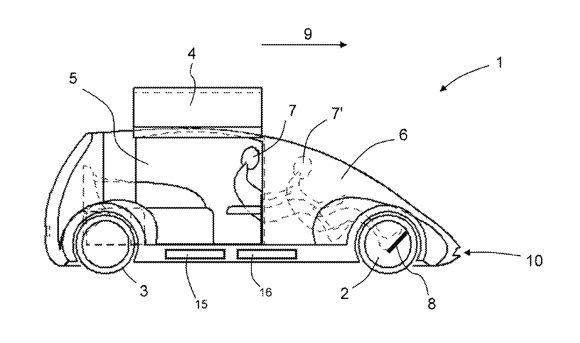
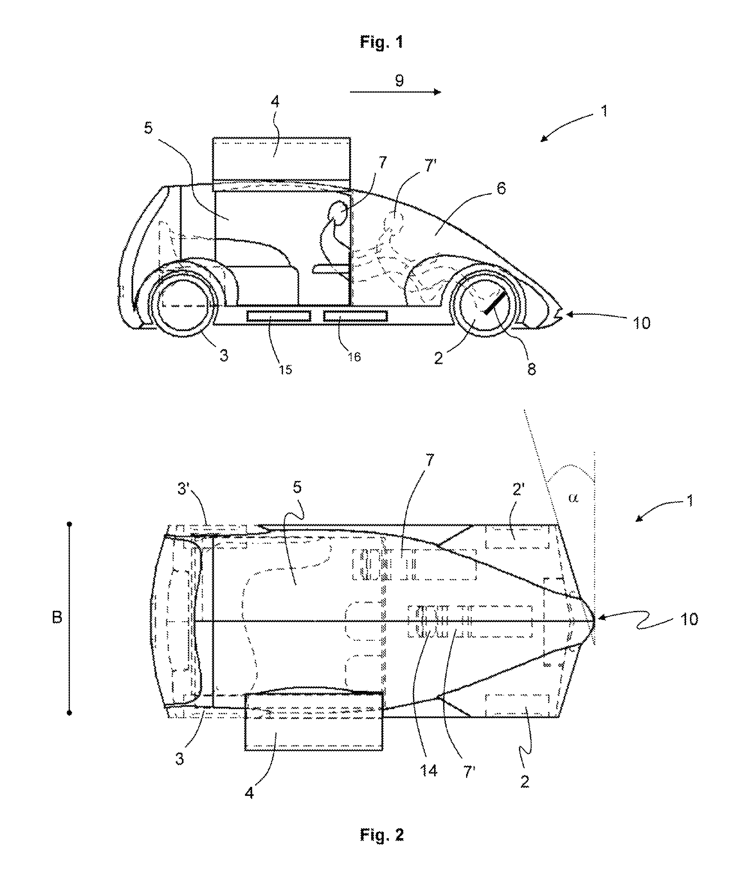
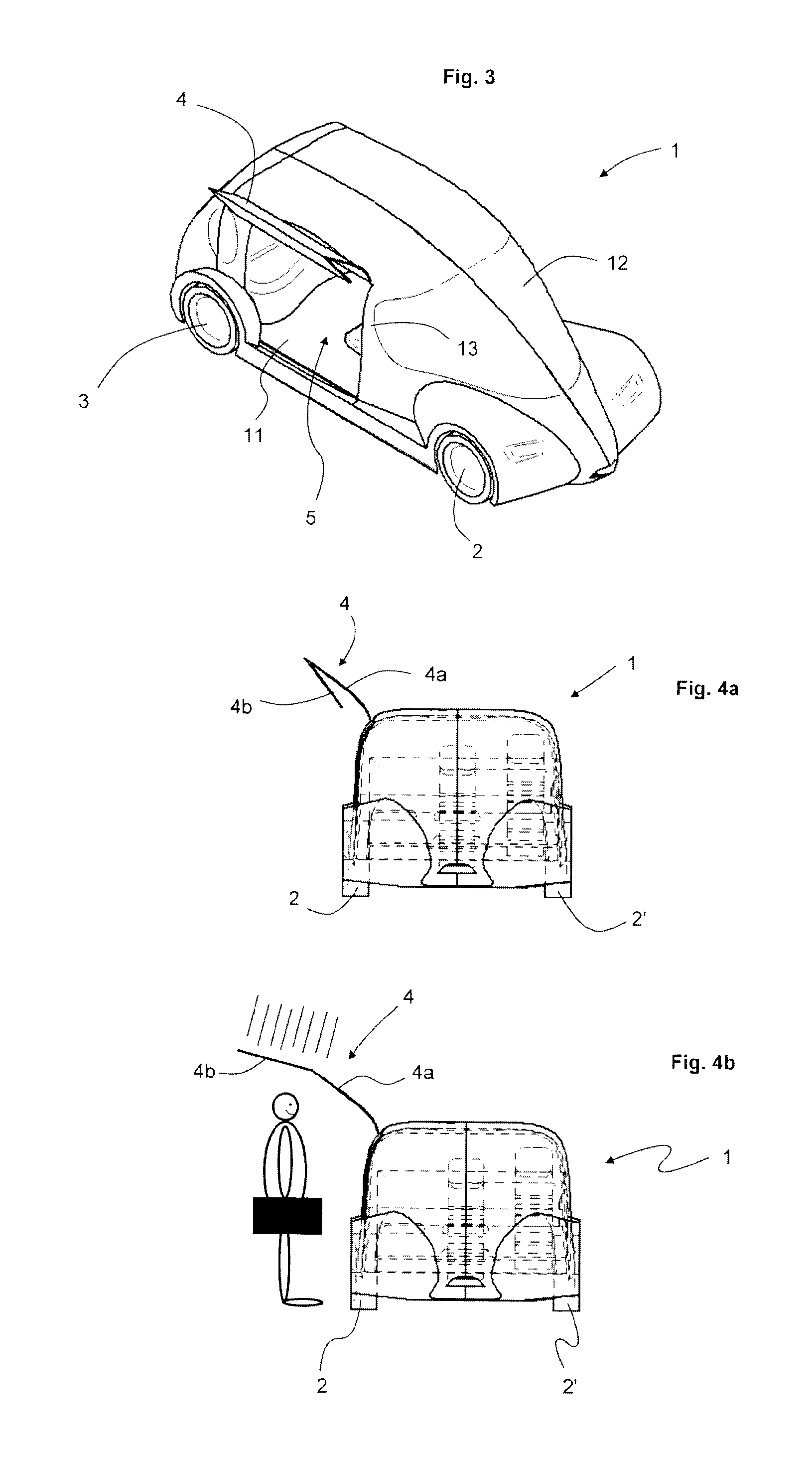
[0029]FIG. 1 shows the motor vehicle 1 in a side view. The vehicle 1 has a pair of front wheels 2, 2′ and a pair of rear wheels 3, 3′, a door 4, a passenger compartment 5 as well as a driver's cab 6, where the driver sits in the positions 7, 7′ shown when driving. In conventional vehicles, the driver adopts the position 7 which is considerably to the rear of the pair of front wheels 2, 2′, as generally the motorized and bulky drive is arranged in front of the driver. According to a practical embodiment of the present invention, however, the driver adopts the position 7′ so that, viewed in the direction of travel 9, the foot pedal 8 is arranged at the rear edge of the front tires 2, 2′. As a result, the passenger compartment 5 gains a considerable amount of space which may be used for transport purposes by passengers and / or luggage. A battery 15 is connected to the vehicle 1.

[0030]Moreover, the stagnation point 10 which is arranged below the wheel axles may be seen in FIG. 1. In the ...


PUM


Abstract

A motor vehicle for use in chauffeur operation, in particular a taxi or a limousine, has at least one driver's seat, at least one foot pedal and at least two front wheels. In order to design a vehicle to meet the specific requirements of short-distance chauffeur operation, the driver's seat is arranged between the front wheels in such a way that the foot pedal is positioned, viewed in the driving direction, between the axles, preferably in front of the front wheel axle.

Description

CROSS REFERENCE TO RELATED APPLICATIONS[0001]This application is a United States National Phase Application of International Application PCT / EP2013 / 068597 filed Sep. 9, 2013 and claims the benefit of priority under 35 U.S.C. §119 of German Patent Application DE 10 2012 018 500.6 filed Sep. 18, 2012, the entire contents of which are incorporated herein by reference.FIELD OF THE INVENTION[0002]The present invention relates to a motor vehicle for use in chauffeur operation, in particular a taxi or a limousine, having at least one driver's seat, at least one foot pedal and at least two front wheels.BACKGROUND OF THE INVENTION[0003]Taxis travel primarily in city traffic and are put to completely different uses from normal passenger vehicles. The distances traveled are relatively short, the proportion of time for the process of the embarking and disembarking of passengers is considerably greater, the comfort of the passengers over long distances is considerably less important relative to ...

Claims


Application Information

Patent Timeline
Patent Type & Authority Patents(United States)
IPC IPC(8): B62D25/20E05B77/02B60K5/00B62D31/00B60J5/04B60N2/01B60J1/00B62D25/04B60K1/04
CPCB62D25/04B60N2/01B62D31/00B60J5/0473B60K5/00B60K1/04B60J5/0498B60J1/008E05B77/02B60K2005/006B60K2001/0438B60L50/66B60L53/80Y02T10/70Y02T10/7072
Inventor FISCHER, HERWIG
Owner HEBEI D DYNAMIC NEW ENERGY CAR RPORATION
Why Eureka
Try Eureka