Fail-safe parking brake for motor vehicles

a parking brake and failure-safe technology, applied in the direction of brake systems, brake components, instruments, etc., can solve the problems of complex parking brake systems, high cost, and inability to guarantee self-locking, so as to improve reliability, reduce cost, and improve reliability

Active Publication Date: 2016-08-30
CONTINENTAL TEVES AG & CO OHG
View PDF28 Cites 17 Cited by
  • Summary
  • Abstract
  • Description
  • Claims
  • Application Information

AI Technical Summary

Benefits of technology

[0016]According to another particularly preferred embodiment of the invention, at least one of the arithmetic units is in the form of a microcontroller with asynchronous redundancy, wherein two processor cores at least partly engage common devices, in particular a volatile or non-volatile memory with parity checking. Here the components having the highest probability of a fault can be implemented as redundant or duplicated. An increase in the reliability with asynchronous redundancy is thus connected to a lower cost than with core redundant microcontrollers.
[0017]According to another particularly preferred embodiment of the invention, at least one of the arithmetic units is in the form of a microcontroller protected by a watchdog counter, which implements two processes that monitor each other. Said version provides inter alia increased reliability compared to a simple microcontroller at low cost by means of the identification of endless loops.
[0018]It is advantageous if two arithmetic units are used with different high degrees of redundancy, so that e.g. safety-relevant programs are executed by a core-redundant microcontroller, while comfort functions are provided by a simple microcontroller.
[0019]Advantageously, at least two independent drive circuits for electric parking brake actuators, in particular pulse width modulation circuits and bridge circuits, are provided, each having an associated power supply, each pref

Problems solved by technology

Furthermore, modern internal combustion engines and gearboxes are frequently designed with low friction in such a way that self-locking, which would allow parking on a hill wit

Method used


Image

  • Fail-safe parking brake for motor vehicles
  • Fail-safe parking brake for motor vehicles
  • Fail-safe parking brake for motor vehicles

Examples


Embodiment Construction

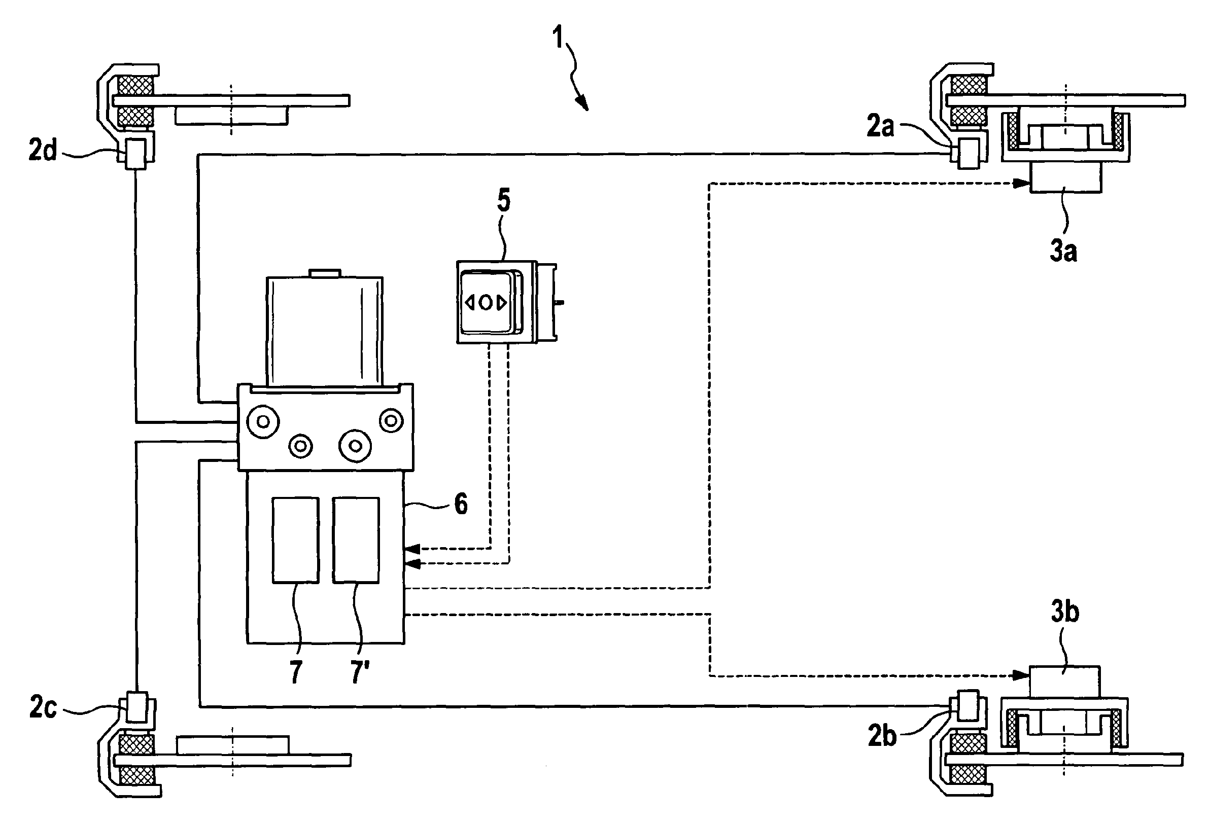
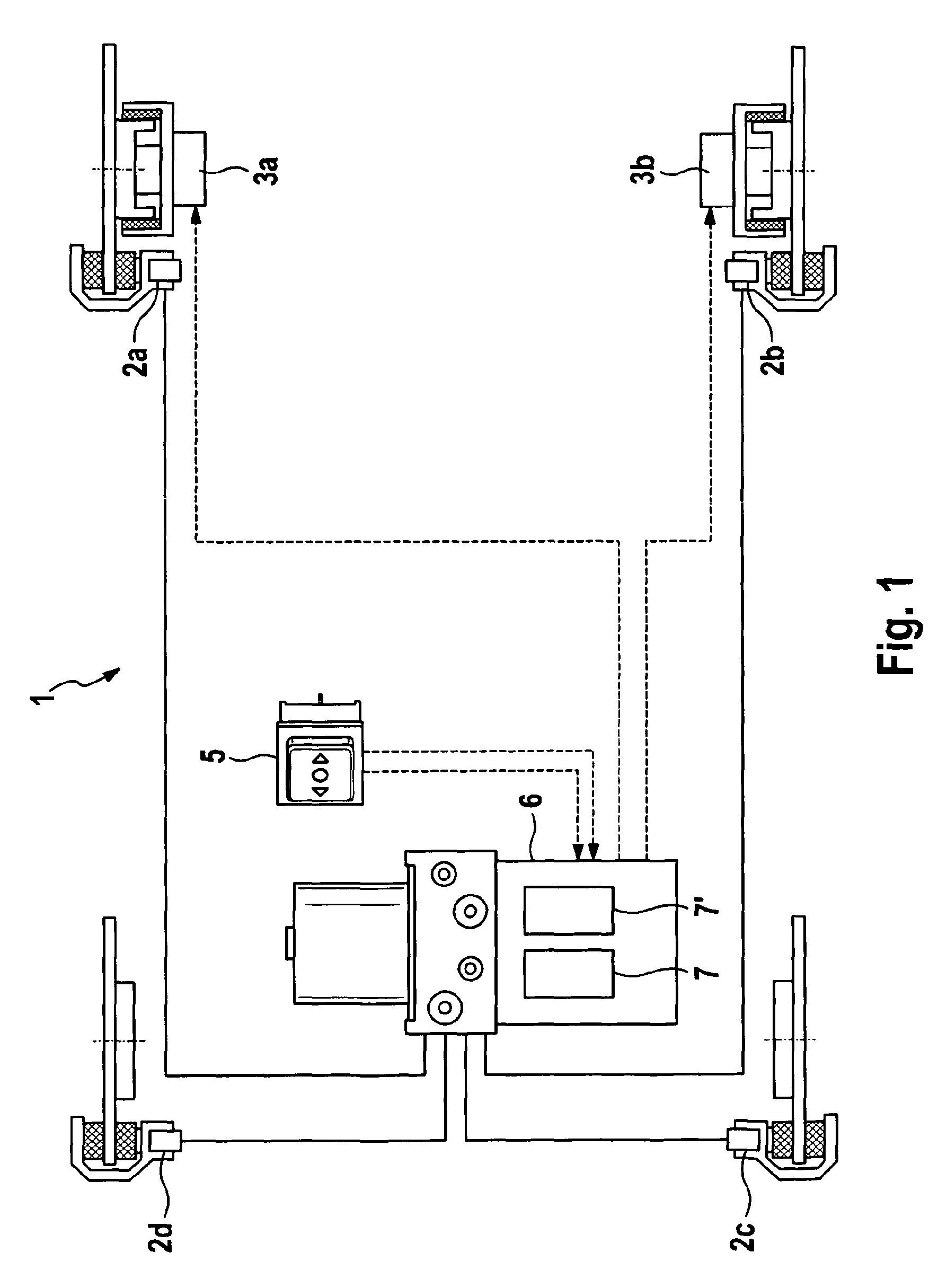
[0039]FIG. 1 shows in schematic form an example of a brake system 1, which is equipped with a service brake on all wheels and a parking brake on two wheels. Here the wheels of the rear axle are equipped with hydraulic friction brakes 2a, 2b and electrical parking brake actuators 3a, 3b, while the wheels of the front axle comprise only hydraulic friction brakes 2c, 2d. Both the service brake and also the parking brake are connected to an electronic controller 6, which comprises two independent arithmetic units, 7, 7′ and receives a driver's command for the operation of the electric parking brake via a parking brake control switch 5.

[0040]The service brake can comprise hydraulic friction brakes or wholly or partly electromechanical brakes. The controller 6 according to the invention enables a fail-safe parking brake both with a purely hydraulic service brake and also with a combination brake, which e.g. comprises hydraulic brakes on the front axle and electromechanical friction brakes...


PUM


Abstract

An electronic controller for a brake system of a motor vehicle, having at least one interface to a control element, in particular a parking brake control switch, and at least two drive circuits for electric parking brake actuators. The electronic controller at least two independent arithmetic units, which are directly connected to each other via a data bus. A motor vehicle equipped with a controller according to the invention requires no transmission lock in an automatic gearbox.

Description

CROSS REFERENCE TO RELATED APPLICATIONS[0001]This application claims priority to German Patent Application Nos. 10 2010 042 595.8, filed Oct. 18, 2010; 10 2011 084 534.8, filed Oct. 14, 2011; and PCT / EP2011 / 068065, filed Oct. 17, 2011.FIELD OF THE INVENTION[0002]The invention relates to a motor vehicle brake system and an electronic controller for such a brake system.BACKGROUND OF THE INVENTION[0003]Modern motor vehicles often comprise an electric parking brake. This can be operated by the driver by means of a control switch that is connected to an electronic controller, which controls one common or two separate parking brake actuators for two wheels. For safety reasons, it is desirable that the electric parking brake operates reliably even in the event of single faults occurring.[0004]An electromechanical parking brake system for motor vehicles is known from DE 197 51 431 A1, which comprises a brake actuating device, an electronic controller for the conversion of input signals into...

Claims


Application Information

Patent Timeline
IPC IPC(8): B60T7/00B60T7/04B60T7/12B60T7/10B60T17/22B60T13/74B60T13/58
CPCB60T7/042B60T7/045B60T7/107B60T13/588B60T13/741B60T13/745B60T13/746B60T13/748B60T17/221B60T7/12B60T2270/413B60T7/10B60T8/17B60T8/1755B60T13/66B60T13/74B60T17/22
Inventor HEISE, ANDREASSCHADE, KAI
Owner CONTINENTAL TEVES AG & CO OHG
Why Eureka
Try Eureka