Automatic transmission

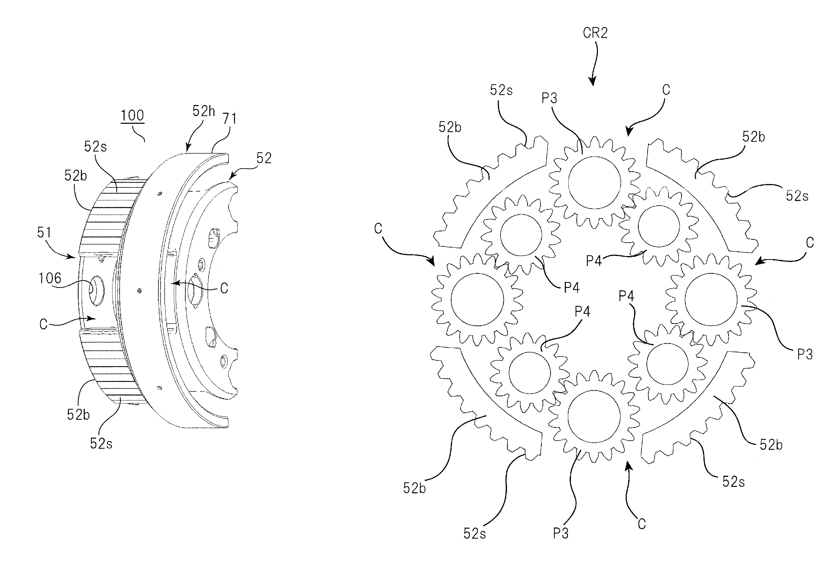
a transmission and automatic technology, applied in the direction of gearing details, gearing, transportation and packaging, etc., can solve the problems of limiting the radial direction of the automatic transmission, affecting affecting the mounting position of the automatic transmission on the vehicle, so as to and improve the torsional rigidity of the carrier body having the bridge portions

Active Publication Date: 2016-08-30
AISIN AW CO LTD
View PDF12 Cites 6 Cited by
  • Summary
  • Abstract
  • Description
  • Claims
  • Application Information

AI Technical Summary

Benefits of technology

[0006]In the automatic transmission according to Patent Document 1, in addition, the clutch on the extending portion of the carrier cover and the brake on the drum portion of the carrier body are disposed side by side in the axial direction, which increases the axial dimension of the automatic transmission.
[0007]Therefore, the present embodiment has been made to address the foregoing issues by improving the structure of a Ravigneaux type carrier, and has an object to provide an automatic transmission capable of enhancing the torsional rigidity of the carrier and suppressing an increase in size of the carrier in the radial direction.Means for Solving the Problem
[0021]According to an embodiment, the structure of the carrier includes the carrier body in which the flange portion, the thick-walled portions, and the bridge portions are formed integrally, and the carrier cover fixed to the distal ends of the bridge portions. Thus, the torsional rigidity of the carrier can be enhanced compared to that according to the related art (such as that described in Patent Document 1). In addition, the openings are provided on the radially outer side of the long pinion gear housing spaces, and only the radially outer side of the short pinion gear housing spaces is covered by the bridge portions. Thus, the bridge portions which couple the carrier body and the carrier cover to each other can be disposed on the radially inner side compared to those according to the related art (such as those described in Patent Document 1). With a combination of such features, the friction engagement element having the friction member engaged with the splines formed on the outer peripheral surfaces of the bridge portions can also be formed on the radially inner side, which makes it possible to make the automatic transmission compact, in particular in dimension in the radial direction. In addition, lubricating oil supplied from the center shaft side is supplied from the openings to the friction engagement element.
[0022]According to another embodiment, the annular member is fixed on the outer peripheral portions of the bridge portions on the side of the thick-walled portions. Thus, the rigidity of the carrier body having the bridge portions alternated with the openings to extend in a comb teeth shape can be improved.
[0023]According to another embodiment, the annular member has the cylindrical portion on the side of the thick-walled portions, and the engagement element such as a one-way clutch is mounted to the cylindrical portion. This enables the engagement element to be positioned on the radially inner side of the cylindrical portion, and to be disposed at a position at which the engagement element overlaps a ring gear engaged with the long pinion gears in the axial direction as viewed in the radial direction and side by side with the friction engagement element in the axial direction, which makes it possible to make the automatic transmission compact.
[0024]According to another embodiment, the annular member has the hub member extending toward the bridge portions. This enables a so-called two-storied structure in which the different friction engagement element engaged with the hub member is disposed on the radially outer side of the friction engagement element. In combination of the reduction in diameter of the carrier, the automatic transmission can be made compact, and the mountability of the automatic transmission on vehicles can be improved. In addition, the different friction engagement element (a brake, for example) is disposed on the radially inner side, and the diameter of the different friction engagement element does not become excessively large, which prevents a reduction in transfer efficiency with drag torque limited in a predetermined range.

Problems solved by technology

In such a case, however, the outside diameter of the carrier (carrier cover) is increased, which hinders the automatic transmission from becoming compact in the radial direction.
This may make it difficult to mount the automatic transmission on a vehicle.

Method used


Image

  • Automatic transmission
  • Automatic transmission
  • Automatic transmission

Examples


Embodiment Construction

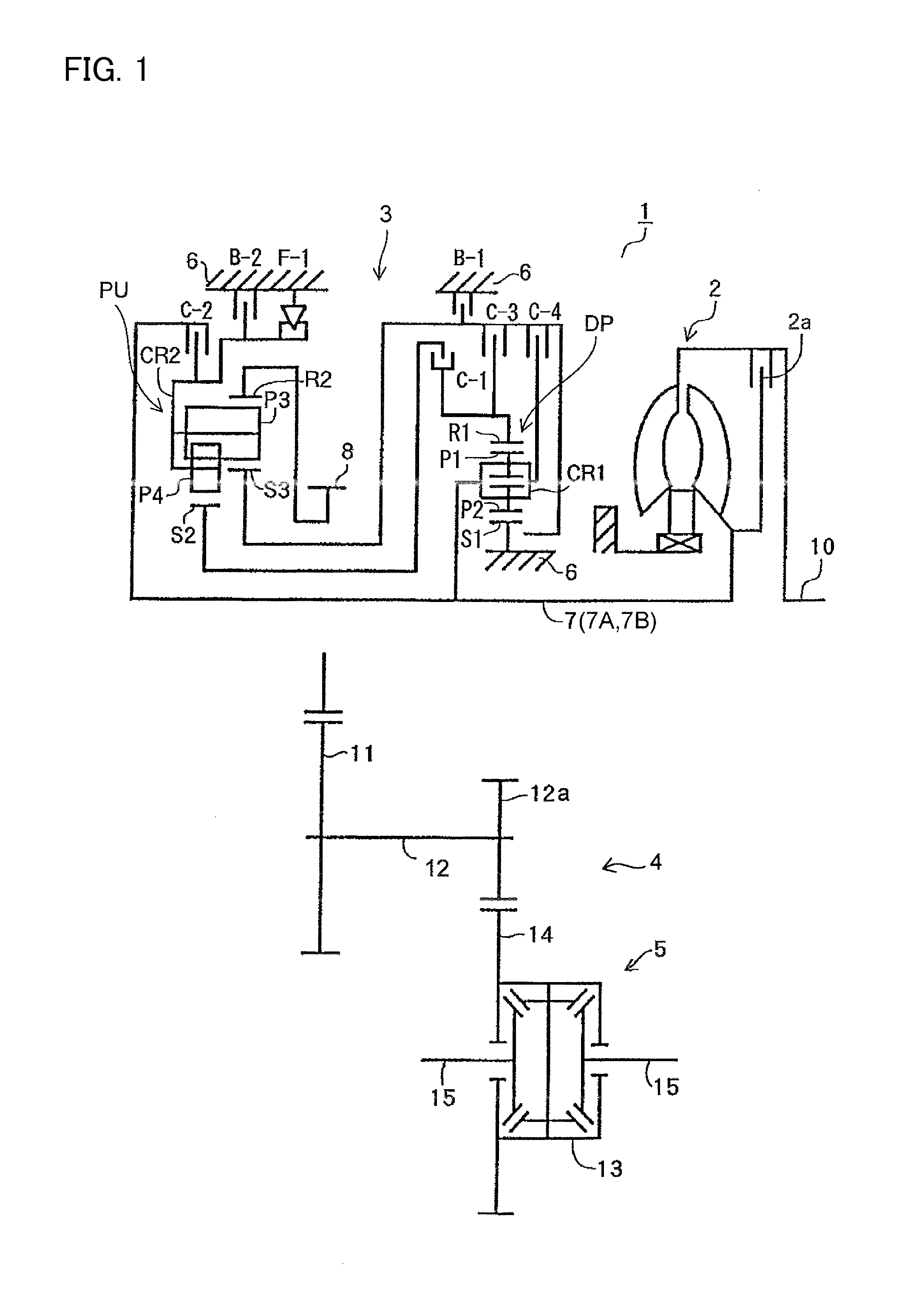
[0031]An embodiment will be described below with reference to FIGS. 1 to 3. An automatic transmission according to the present embodiment is an automatic transmission that is suitably mounted on FF (front-engine front-drive) vehicles, for example. The left-right direction in FIGS. 1 and 3 corresponds to the left-right direction (or the direction opposite to the left-right direction) with the automatic transmission actually mounted on a vehicle. For convenience of description, however, the right side of the drawings on which a drive source such as an engine is provided is referred to as “front side”, and the left side of the drawings is referred to as “rear side”.

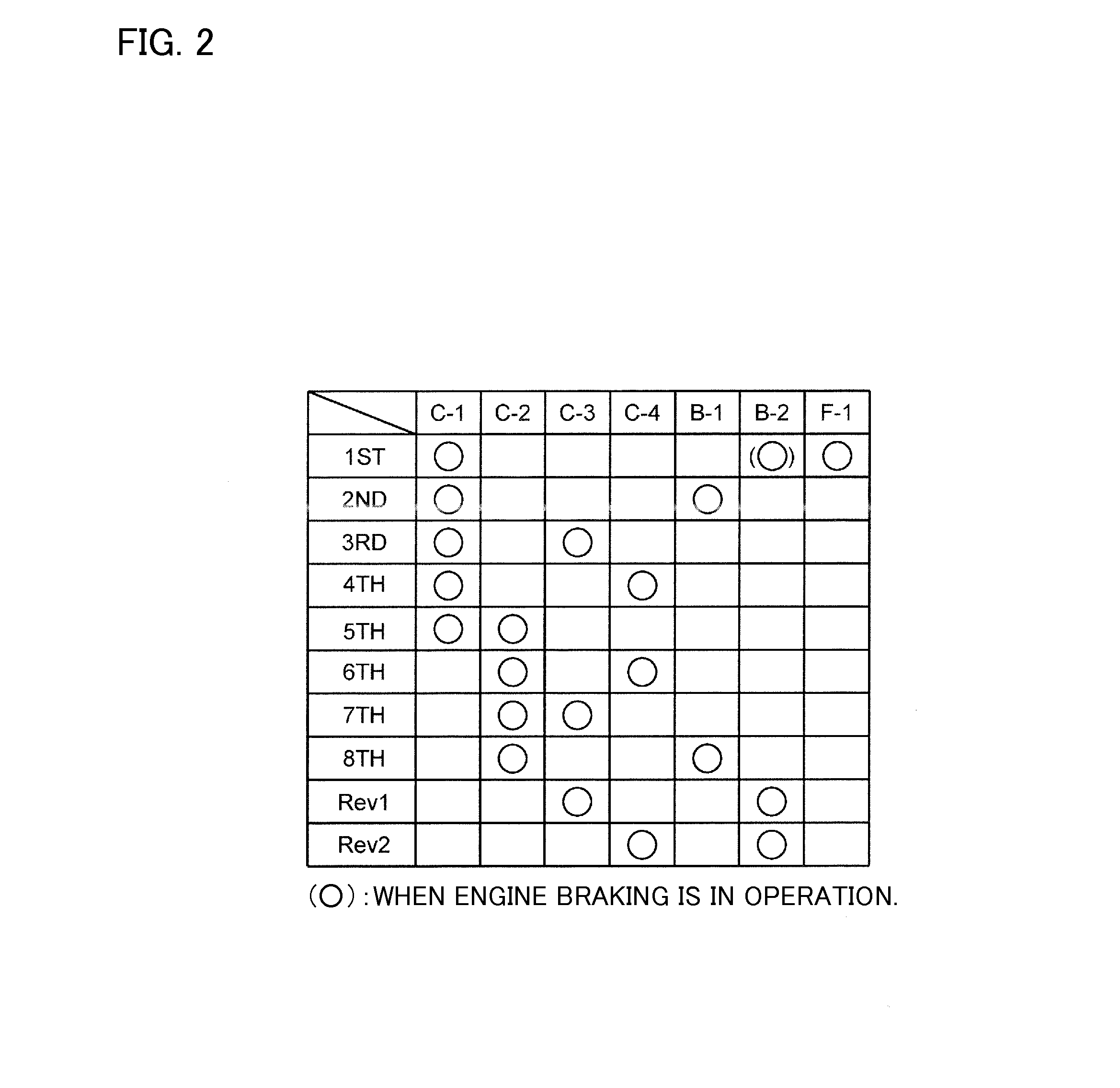
[0032]First, a schematic configuration of an automatic transmission 1 to which the present embodiment may be applied will be described with reference to FIG. 1. As illustrated in FIG. 1, the automatic transmission 1, which is suitable for use in FF (front-engine front-drive) vehicles, for example, includes a torque converter...


PUM


Abstract

A carrier having short pinion gears and long pinion gears is made compact, and the mountability of the carrier on vehicles is improved. In a structure of the carrier, short pinion gear housing spaces are formed between thick-walled portions of a carrier body and a carrier cover, and long pinion gear housing spaces are formed between flange portions and the carrier cover. Bridge portions are provided on the radially outer side of the short pinion gear housing spaces, and fixed to the carrier cover. Openings are provided on the radially outer side of the long pinion gear housing spaces. Splines to be engaged with a friction member of a clutch are formed on the outer peripheral surfaces of the bridge portions.

Description

CROSS REFERENCE TO RELATED APPLICATIONS[0001]This application is a National Stage of International Application No. PCT / JP2013 / 081166 filed Nov. 19, 2013, claiming priority based on Japanese Patent Application No. 2012-253754, filed Nov. 19, 2012, the contents of all of which are incorporated herein by reference in their entirety.TECHNICAL FIELD[0002]The present subject matter relates to an automatic transmission to be mounted on an automobile, for example, and particularly to an automatic transmission including a carrier (hereinafter referred to as a Ravigneaux type carrier or simply as a carrier) having short pinion gears and long pinion gears.BACKGROUND ART[0003]Hitherto, there has been an automatic transmission including a Ravigneaux type planetary gear including a carrier having short pinion gears and long pinion gears, and a clutch provided at the outer periphery of the carrier (Patent Document 1). In the automatic transmission, eight forward speeds and two reverse speeds are e...

Claims


Application Information

Patent Timeline
Patent Type & Authority Patents(United States)
IPC IPC(8): F16H57/08F16H3/66
CPCF16H57/082F16H3/663F16H3/666F16H2200/006F16H2200/0086F16H2200/2007F16H2200/2023F16H2200/2046F16H2200/2066F16H2200/2097F16H2200/2082F16H2057/087
Inventor IKE, NOBUKAZUTORII, TAKESHISANJI, HIROAKIDEGUCHI, TSUBASA
Owner AISIN AW CO LTD
Why Eureka
Try Eureka