Part inspection apparatus and handler

a technology of inspection apparatus and handler, which is applied in the direction of instruments, furniture, charge manipulation, etc., can solve the problems of increased consumption of dry gas, increased temperature difference between the surface of the device and the outside air, and condensation of dew

Active Publication Date: 2016-09-06
NS TECH INC
View PDF10 Cites 1 Cited by
  • Summary
  • Abstract
  • Description
  • Claims
  • Application Information

AI Technical Summary

Benefits of technology

[0006]An advantage of some aspects of the invention is that a part inspection apparatus configured to restrain occurrence of dew condensation on an object to be transferred while reducing the consumed amount of dry gas when the object to be transferred is transferred, and a handler are provided.
[0009]According to the configurations of the one aspect of the part inspection apparatus and the one aspect of the handler according to the invention, the transfer robot configured to transfer the object to be transferred cooled on the placing portion includes the housing member configured to accommodate the object to be transferred held on the holding portion, and the dry gas is supplied into the housing member. Therefore, when the object to be transferred is transferred by the transfer robot, the object to be transferred is held in a space to which the dry gas is supplied, so that the object to be transferred is restrained from coming into contact with gas on the outside of the housing member. Therefore, even though the dry gas is not supplied to the entire space where the cooled object to be transferred is transferred, the dew condensation occurring on the surface of the object to be transferred may be restrained when the object to be transferred is transferred.
[0011]According to the another aspect of the part inspection apparatus of the invention, since the second housing member configured to accommodate the placing portion and the first housing member configured to accommodate the object to be transferred and the holding portion are connected, the object to be transferred is further restrained from coming into contact with the housing member and the gas on the outside of the housing box. Therefore, the dew condensation occurring on the surface of the object to be transferred is further restrained.
[0017]According to the yet another aspect of the handler of the invention, since the second dry gas supply unit includes the dry gas heating unit configured to heat the cooling medium, the cooling medium heated by the dry gas heating unit is supplied to the second housing member as the dry gas described above. Accordingly, since the temperature of the gas supplied into the second housing member is further restrained from decreasing to a dew point or below, the dew condensation hardly occurs on the surface of the object to be transferred in the second housing member. In addition, decrease of the temperature of a member which constitutes an outer surface of the second housing member to a dew point of the outside atmosphere of the second housing member or below may easily be restrained, so that dew condensation on the member which constitutes the outer surface of the second housing member can easily be restrained.
[0019]According to the still yet another aspect of the handler of the invention, the first housing member and the second housing member each include an opening configured to allow passage of the holding portion of the transfer robot and the object to be transferred held by the holding portion. Therefore, when the object to be transferred placed on the placing portion is accommodated in the first housing member, the object to be transferred is transferred via the openings formed in the second housing member and the opening formed in the first housing member. Therefore, in comparison with the configuration in which transfer from the placing portion to the first housing member is performed by opening and closing the first housing member or the second housing member by itself, the configurations of the first housing member and the second housing member may further be simplified. In addition, the object to be transferred is further restrained from coming into contact with the gas on the outside of the first housing member and the second housing member, and hence the dew condensation further hardly occurs on the surface of the object to be transferred.
[0023]According to the still further another aspect of the handler of the invention, the sensor configured to detect the characteristics of gas in the first housing member, for example, temperature or moisture, is provided. Then, the flow amount of the dry gas supplied from the first dry gas supply unit to the first housing member is changed on the basis of the result of detection of the sensor. Therefore, in comparison with the configuration in which such a sensor is not provided, characteristics in the first housing member at the time of detection by the sensor is reflected on the flow rate of dry gas to be supplied into the first housing member. Therefore, the characteristics of the gas in the first housing member can easily be maintained in predetermined conditions, and hence the interior of the first housing member can easily be maintained in an environment which does not cause dew condensation on the surface of the object to be transferred.

Problems solved by technology

Incidentally, since the part inspection apparatus is generally installed in an environment maintained at a constant temperature, a temperature difference between the surfaces of the devices and the outside air is created and dew condensation occurs on the surfaces of the devices when the devices taken out from the constant temperature reservoir are transferred to the tester.
However, since a supply of dry gas to the above-described chamber is required, the amount of consumption of the dry gas is inevitably increased.

Method used


Image

  • Part inspection apparatus and handler
  • Part inspection apparatus and handler
  • Part inspection apparatus and handler

Examples


first embodiment

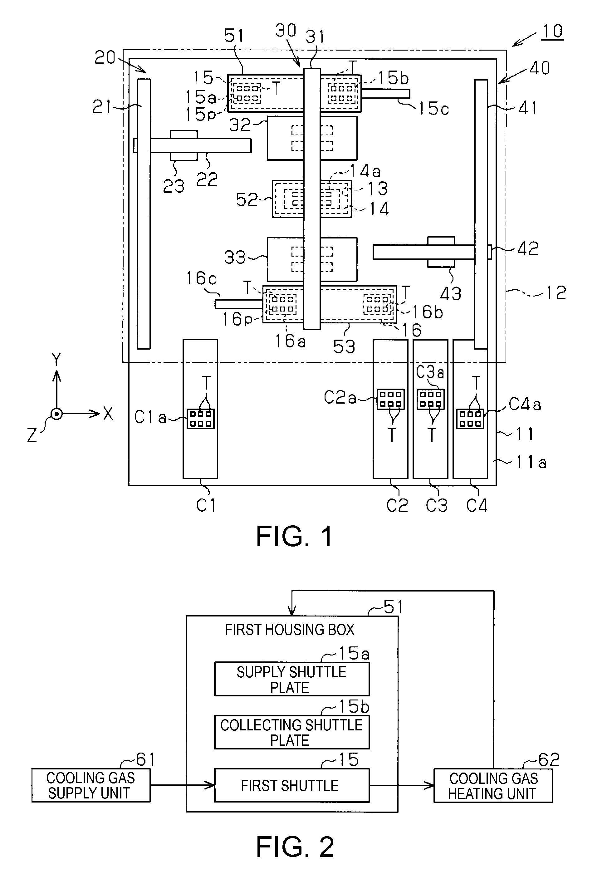
[0040]Referring now to FIG. 1 to FIG. 7, a part inspection apparatus and a handler of a first embodiment of the invention will be described below. First of all, a general configuration of the handler and the part inspection apparatus will be described with reference to FIG. 1.

Configurations of Handler and Part Inspection Apparatus

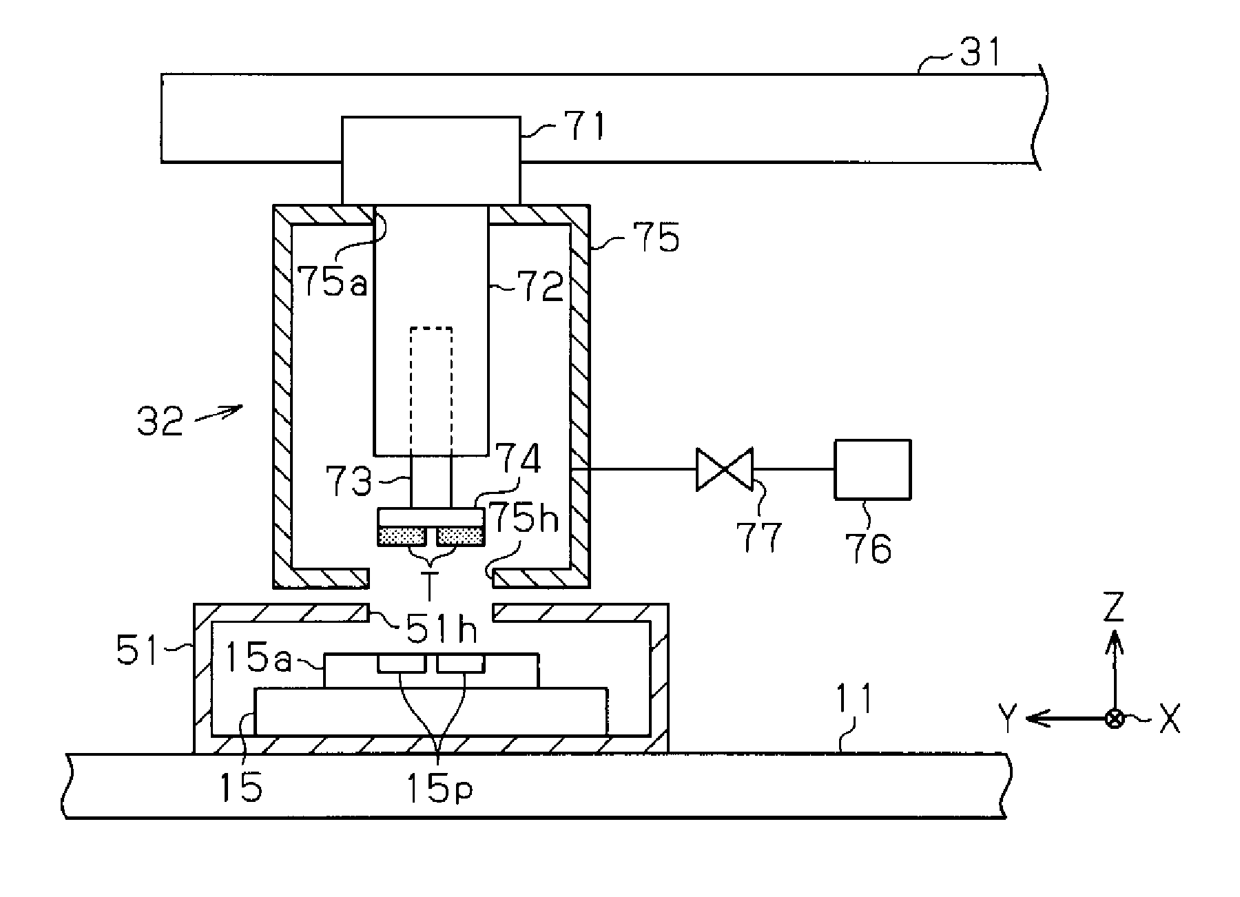
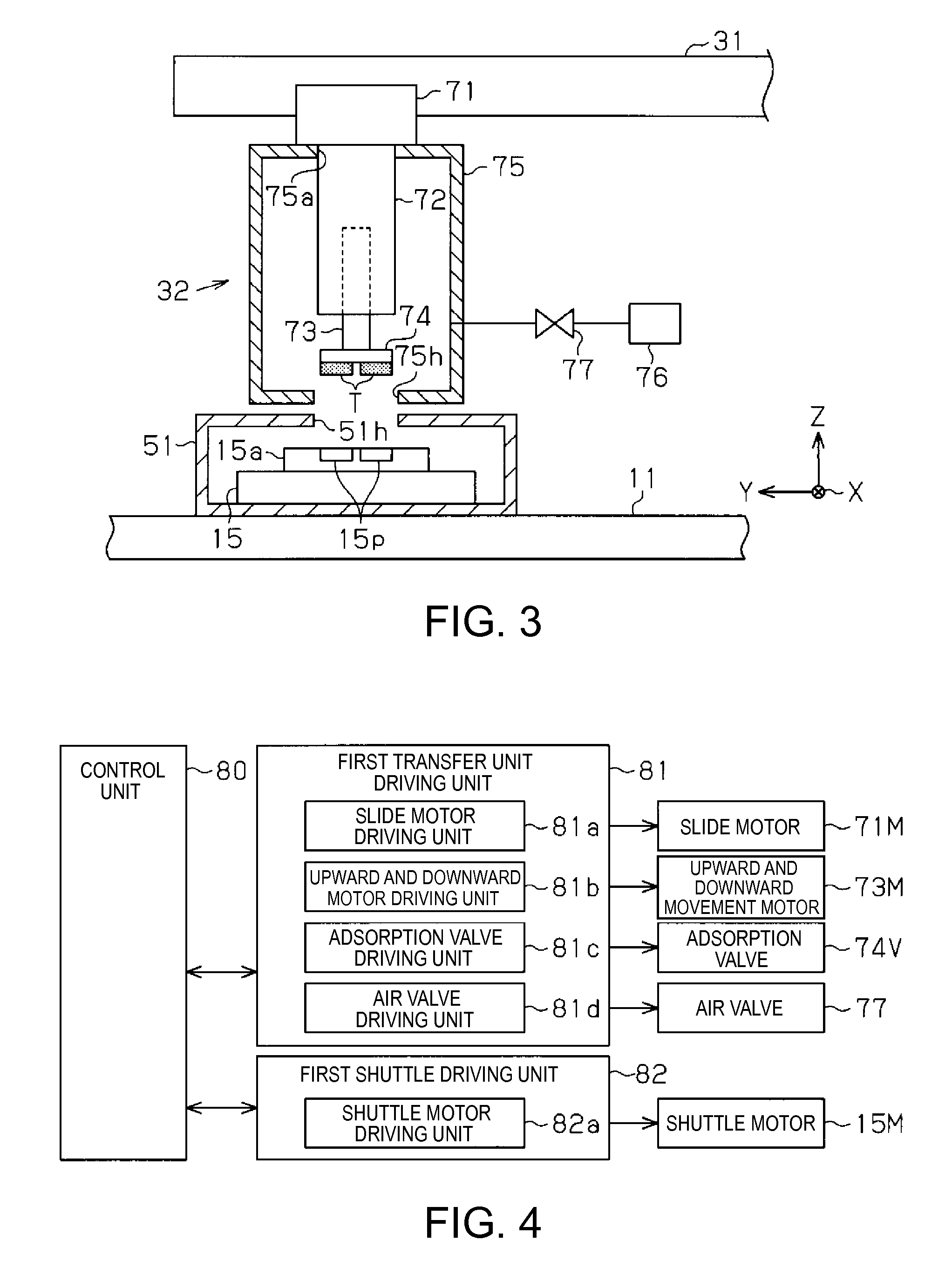
[0041]As illustrated in FIG. 1, a base 11 of a handler 10 is provided with a mounting surface 11a as an upper surface on which various robots are mounted, and most part of the mounting surface 11a is covered with a cover member 12. Atmospheric air maintained at a normal temperature, for example, at 18° C., is supplied from the outside in a transfer space which is a space surrounded by the mounting surface 11a and the cover member 12.

[0042]Four conveyers C1 to C4 configured to transfer devices T as objects to be transferred are arranged on the mounting surface 11a of the base 11 between the outside and the inside of the cover member 12. On one side in an X d...

second embodiment

[0095]Referring now to FIG. 8 to FIG. 15, apart inspection apparatus and a handler according to a second embodiment of the invention will be described below. For reference, the handler and the part inspection apparatus of the second embodiment are different from the handler and the part inspection apparatus of the first embodiment described above in the configurations of the transfer units 32 and 33 of the transfer robot 30 and the respective boxes 51 to 53. Therefore, the different configurations are described in the following description and description of other configurations is omitted.

Configuration of Transfer Robot and Housing Box

[0096]As illustrated in FIG. 8, the first housing box 51 has a box shape that accommodates the first shuttle 15 and the supply shuttle plate 15a in the interior thereof in the same manner as that of the first embodiment. The rectangular-shaped opening 51h which allows passage of the adsorbing portions 74 of the first transfer unit 32 is provided immed...


PUM


Abstract

A handler includes a supply shuttle plate on which a device is placed and cooled, and a transfer robot configured to transfer the device placed on the supply shuttle plate from the supply shuttle plate. The transfer robot includes an adsorbing portion configured to adsorb the device placed on the supply shuttle plate thereon, a vertical movement arm configured to move the adsorbing portion away from the supply shuttle plate, an arm box configured to accommodate the adsorbing portion together with the device in a state of being kept away from the supply shuttle plate, and a dry air supply unit configured to supply dry gas into the arm box.

Description

BACKGROUND[0001]1. Technical Field[0002]The present invention relates to a part inspection apparatus and a handler.[0003]2. Related Art[0004]In the related art, a part inspection apparatus configured to transfer devices as an object to be transferred by a handler is widely used for an inspection of electric characteristics with respect to various devices such as semiconductor devices. In the part inspection apparatus, inspection of the devices is performed at temperatures suitable for usage environments of the respective devices, for example, the inspection may often be performed at a low temperature environment such as 0° or below. The part inspection apparatus which performs the inspection under the low temperature environment includes, for example, a constant temperature reservoir configured to cool the devices and a tester configured to perform the inspection while cooling the devices mounted thereon as described in JP-A-2004-347329. Then, in the part inspection apparatus, the d...

Claims


Application Information

Patent Timeline
Patent Type & Authority Patents(United States)
IPC IPC(8): G01R31/28B65G49/00H01L21/67H01L21/683
CPCB65G49/00G01R31/2893H01L21/67109H01L21/6838G01R31/26H01L22/00
Inventor MAEDA, MASAMISHIMOJIMA, TOSHIOKI
Owner NS TECH INC
Why Eureka
Try Eureka