Safety door handle

a door handle and door handle technology, applied in the field of door handle modules, can solve the problems of threatening hazard to the driver, acute and present, and achieve the effect of increasing the safety of the door handle modul

Active Publication Date: 2016-09-06
HUF HULSBECK & FURST GMBH & CO KG
View PDF36 Cites 8 Cited by
  • Summary
  • Abstract
  • Description
  • Claims
  • Application Information

AI Technical Summary

Benefits of technology

[0009]A significant advantage of the present invention is also seen in the fact that the crash lock can remain activated after being activated once, but the door handle can nevertheless be fully activated, in order to be able to rescue a person in the vehicle without problem even after the accident. For this purpose, it is only required to pull more vigorously on the door handle than normally, in order to also overcome the additional force of the additional spring. The altered activation of the door handle also indicates to a driver of the vehicle that the crash lock has been activated.
[0010]In order to be able to adjust the tripping behavior of the crash lock during the action of acceleration forces, an activation spring is provided, which acts exclusively on the crash lock. By appropriate selection of the spring force of the activation spring, the response behavior of the crash lock can therefore be adjusted without problem. By complete separation of the mechanical method of action of the activation spring and the additional spring and the return spring, the desired tripping characteristics of the crash lock and the door module can be set independently of each other without problem for an accident. For this purpose, only the spring force of the corresponding spring must be selected and set or stipulated.
[0011]The crash lock can have at least two positions, namely a deactive position, in which the crash lock is deactivated, and an active position, in which the crash lock is activated. It is then conceivable that the crash lock is held in the active position in shape-mated and / or force-fit fashion by a securing element. For this purpose, the securing element for the crash lock can be a switch spring that keeps the crash lock in the active position and / or the deactive position in force-fit fashion. The switch spring here can simultaneously be the activation spring, as further shown in the following text. Optionally, it is conceivable that the securing element is a securing pin, in which case the securing pin itself is spring-loaded and the securing element secures the crash lock in the active position in shape-mated or also force-fit fashion. For this purpose, a snap-in device, especially in the form of a beveled tip can be provided on the securing pin, which cooperates with a mating snap-in device in the crash lock in shape-mated fashion. This mating snap-in device can include an opening or a recess, into which the securing pin of the active position penetrates in shape-mated fashion.
[0012]Deactivation of the crash lock now occurs in a simple manner, the securing element being transferred to its normal position, so that the crash lock is transferred from the active position to the deactive position. Deactivation of the crash lock can occur, for example, from the outside (the door handle side) through a small slit or opening in the door or hatch, in which case a corresponding tool must be guided through the opening, in order to force the securing element or crash lock from the active position. However, to achieve increased safety, it is recommended to configure the deactivation of the crash lock exclusively performable from the inside of the door (the support frame side). Here again, only the securing element or the crash lock need be transferred from the active position to the deactive position. The door handle module is then fully ready for use again, the additional force being again switched off, since the crash lock is arranged back in the deactive position. The door handle can therefore be operated quite normally again, i.e., merely against the restoring force of the return spring.
[0013]In order to further increase the safety of the door handle module, it can be prescribed that the crash lock has two active positions. The door handle is thus secured against acceleration forces from two different effect directions. For this purpose, the deactive position of the crash lock can be provided between the two active positions, in which case the crash lock is configured rocker-like, which can be transferred from the deactive position into the first or second active position, if an acceleration force acts on the crash lock. It is also conceivable that, instead of the previously mentioned crash lock with an active position, a second crash lock is provided, arranged on the door handle module, so that it trips in the opposite direction to the first crash lock, when an opposite acceleration force (with reference to the first crash lock) acts on the door handle module. The first crash lock can be arranged at or on one end of a pivot of the coupling unit. The second crash lock, on the other hand, can be arranged at or on an opposite end of the pivot of the coupling unit on which the first crash lock can be arranged. It is also conceivable that a shape-mated crash lock, as in the prior art, for example, as disclosed from document DE 199 29 022 C2, is used. This crash lock can be provided as second or as third crash lock in the door handle module according to the invention, in which the first and optionally the second crash lock can represent a switchable shape-mated crash lock. By the use of the shape-mated crash lock, it is ensured that even very high acceleration forces in each case do not lead to activation of the door handle, even if the acceleration forces are much higher than the additional force of the connected additional spring.
[0014]In the context of the invention, it can also be prescribed that an actuating element is present, which mechanically cooperates, on the one hand, with the additional spring for the door handle and, on the other hand, with the crash lock in the active position. The actuating element here can be mounted on the support frame or on the mechanical coupling unit. Other embodiments of the crash lock, the securing element and the actuating element are also naturally conceivable in the context of kinematic reversal.

Problems solved by technology

However, current accident research results have shown that it is precisely during a side impact that alternating acceleration forces can occur, which initiate so-called “fluttering” of the fast-acting crash lock.
The problem therefore arises during actual accidents that the fast-acting crash lock is activated by the acceleration forces acting during an accident and secures the door handle in the rest position, but, during subsequent fluttering of the crash lock, a situation can occur in which the door handle is moved from the rest position by the acting acceleration forces, since the fast-acting crash lock has left its activation position during the fluttering process.
Unfortunately, undesired release of the door lock can therefore occur, so that an acute and threatening hazard to the driver is present.

Method used


Image

  • Safety door handle
  • Safety door handle
  • Safety door handle

Examples


Embodiment Construction

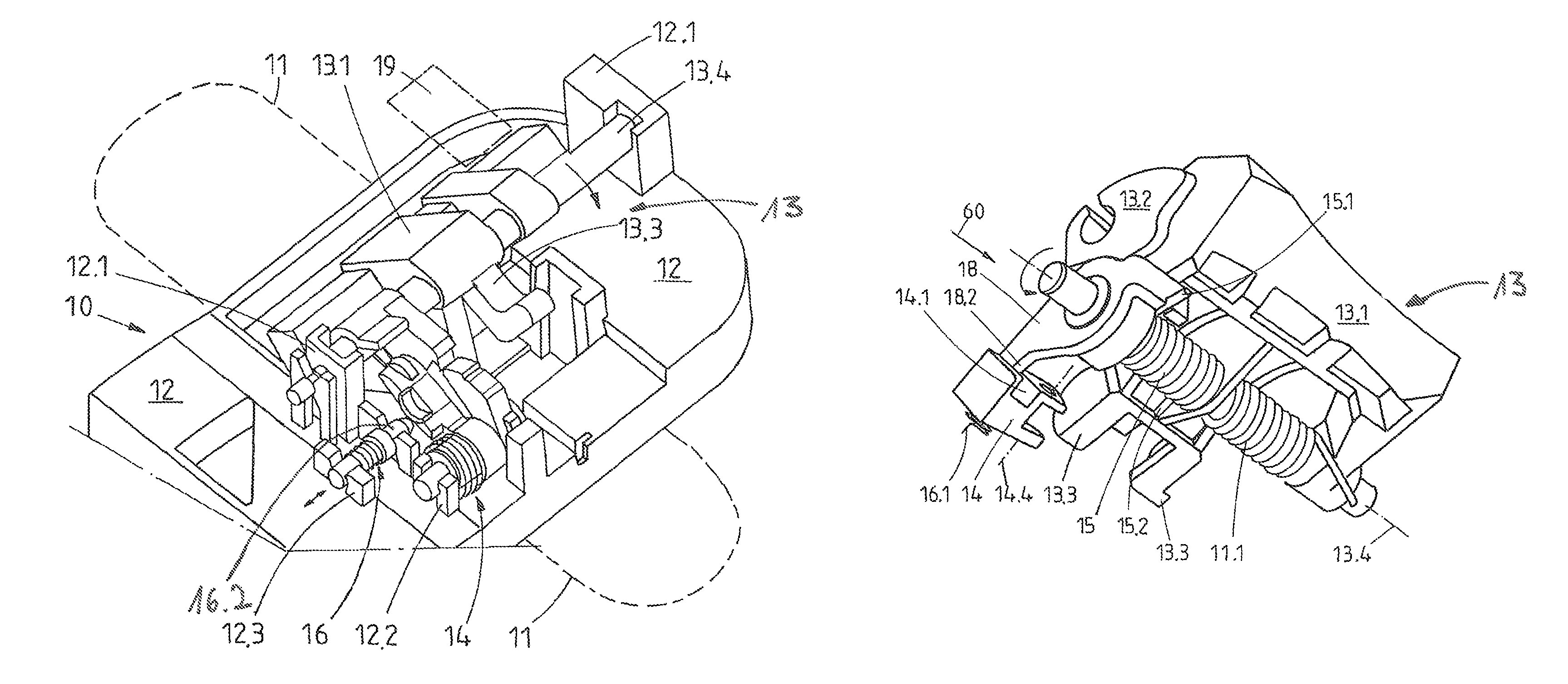
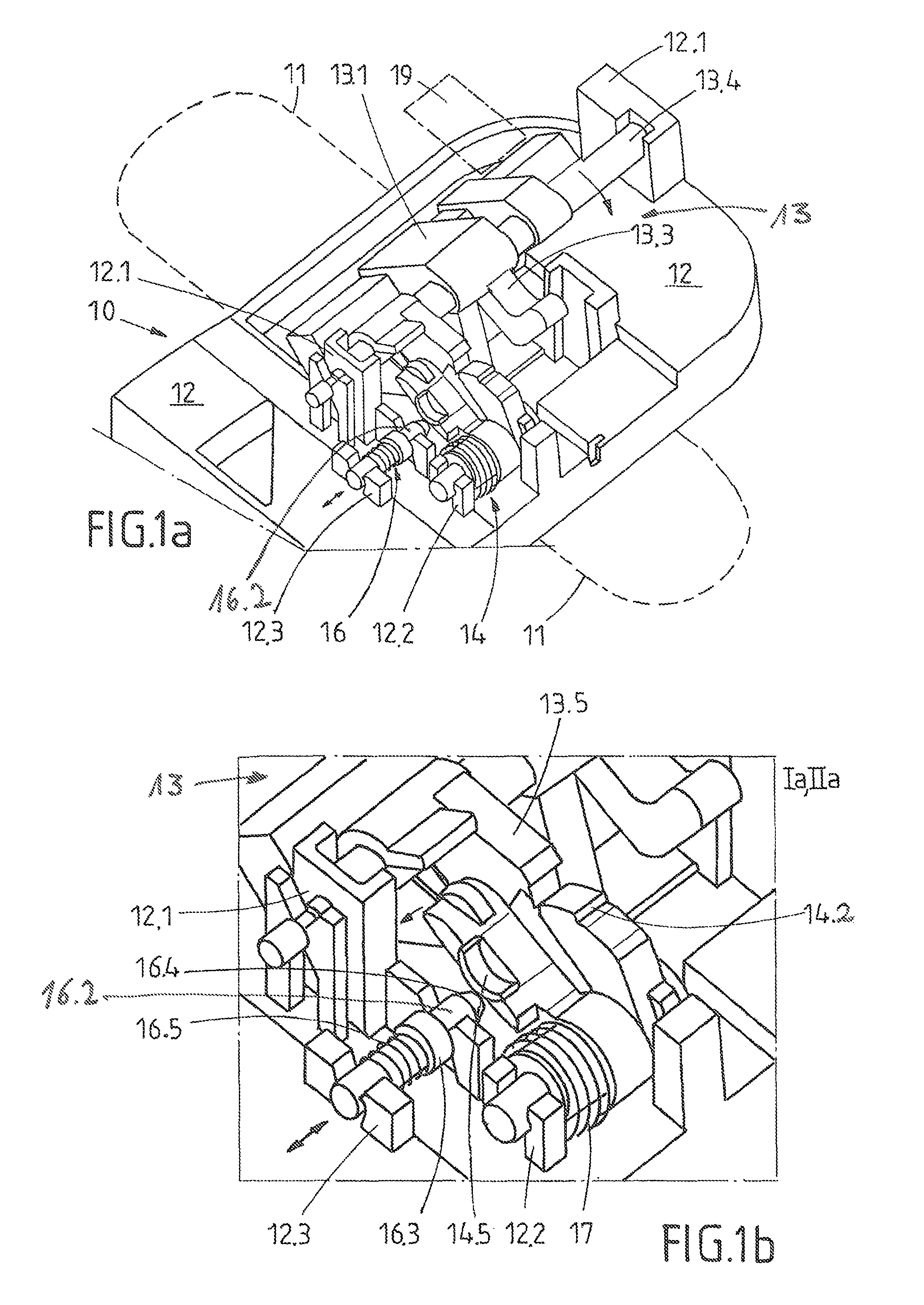
[0040]A first practical example of the door handle model 10 according to the invention for a vehicle is shown in FIG. 1a. The inside view or rear view of the door handle module 10 is then shown, in which the door handle 11 itself has been left out. For this reason, the door handle 11 is only indicated with dashed lines in FIG. 1. The door handle 11 cooperates from the outside with a mechanical coupling unit 13, which is mounted to move on the support frame 12 on the inside of the door. The door handle 11 is mounted to move in the support frame 12 or on the coupling unit 13. In order for a lock in the door to be opened with it, movement of the door handle 11 is transferred directly or indirectly to the lock via a mechanical coupling unit 13 through a transfer element.

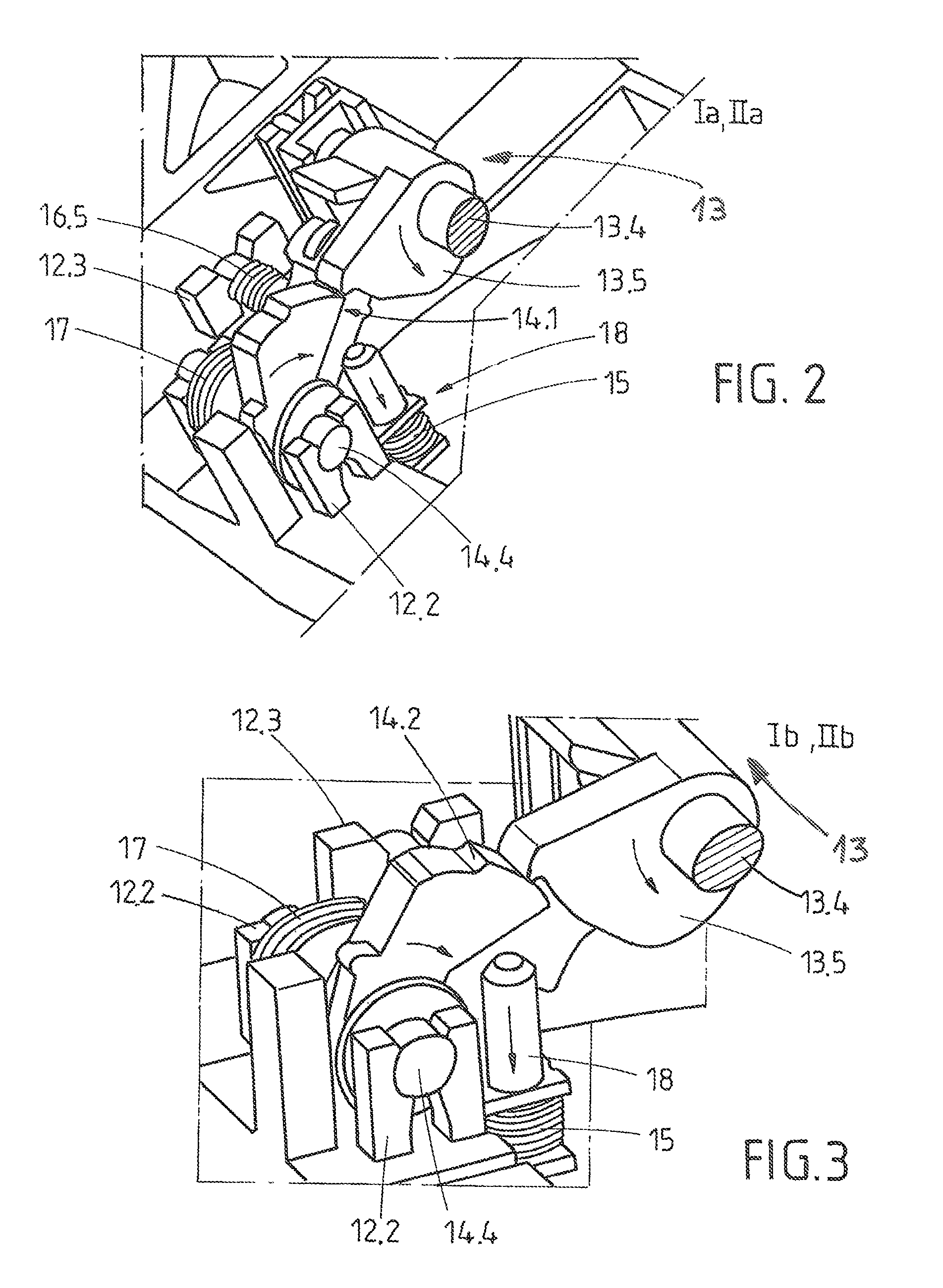
[0041]The door handle module 10 according to the invention is equipped with a crash lock 14, which engages an additional spring 15 during an accident or during the action of acceleration forces. This additional spring 15...


PUM

PropertyMeasurementUnit
forceaaaaaaaaaa
forceaaaaaaaaaa
forceaaaaaaaaaa

Abstract

The invention concerns a door handle module for a vehicle with a door handle, which is mounted to move in a support frame for the opening of a door or hatch by a user, the door handle having at least one rest position and one working position, a mechanical coupling unit, through which movement of the door handle from the rest position to the working position can be transferred to a lock, a crash lock, which prevents movement of the door handle and / or coupling unit during the action of an acceleration force, especially during an accident, so that activation of the lock is avoided.

Description

TECHNICAL FIELD[0001]The present invention is directed toward a door handle module for a vehicle with a door handle that is mounted to move in a support frame for the opening of a door or hatch by a user. The invention is also directed toward a method for securing a door handle module with a door handle that can be mounted to move in a support frame for the opening of a door or hatch by a user. The door handle of such a door handle module has at least one rest position and one working position. The door handle module is also equipped with a mechanical coupling unit, through which movement of the door handle from the rest position to the working position can be transferred to a lock, and with a crash lock, which prevents movement of the door handle and / or coupling unit during the action of an acceleration force, especially during an accident, so that activation of the lock is avoided.BACKGROUND[0002]Document DE 199 29 022 C2 is known from the prior art, which is also directed toward ...

Claims


Application Information

Patent Timeline
Patent Type & Authority Patents(United States)
IPC IPC(8): E05B3/00E05B85/10E05B77/06E05B77/54
CPCE05B85/10E05B77/06Y10T29/49863Y10T292/57
Inventor MULLER, DIRKKALESSE, MICHAELLENNHOFF, RALF
Owner HUF HULSBECK & FURST GMBH & CO KG
Why Eureka
Try Eureka