Capacitance-to-digital converter and method for providing a digital output signal

a technology of capacitance and converter, applied in the direction of code conversion, instruments, analogue conversion, etc., can solve the problems that a cdc cannot achieve the easy achievement of high linearity and high psrr, and achieve high linearity and high accuracy of measurement.

Active Publication Date: 2016-09-06
AMS AG
View PDF18 Cites 11 Cited by
  • Summary
  • Abstract
  • Description
  • Claims
  • Application Information

AI Technical Summary

Benefits of technology

[0007]Advantageously, the calibration unit is used for a calibration that reduces the influence of variations of the input capacitor and the converter during fabrication and the non-linearity of the input capacitor and the converter. The capacitance-to-digital converter is abbreviated as CDC. The calibration unit may be realized as a signal evaluation unit, digital calibration unit or capacitance-to-digital converter calibration unit. The calibration unit may be implemented as a microprocessor or microcontroller. The converter may have a capacitive input.
[0044]The first integrator implemented as a differential switched-capacitor integrator results in a high accuracy of the sigma-delta modulation. The sigma-delta modulator is designed for digitalization of a sensor signal generated by the capacitive sensor. Moreover, a high linearity of a signal chain between a parameter to be measured by the capacitive sensor and a digital sensor signal generated by the sigma-delta modulator can be achieved by the ICMFB circuit. Additionally, the chopping unit contributes to the improvement of the electrical characteristics. Advantageously, the capacitive sensor is part of the circuit of the sigma-delta modulator. Alternatively, the ICMFB circuit may be omitted or disabled.
[0064]By means of chopping the analog sensor signal, the use of a differential switched capacitor integrator and the input common mode feedback, a high accuracy of the measurement by the capacitive sensor is achieved. The input common mode feedback is generated by an input-common-mode feedback circuit.
[0065]Advantageously, the CDC is designed as direct capacitance-to-digital converter. The direct CDC uses a fully-differential architecture to improve PSRR. The CDC performs a digital calibration and / or an input common mode feedback in the first amplifier of the first integrator to obtain a high linearity for the measurement of a capacitance value of the capacitive sensor.

Problems solved by technology

A characteristic such as a high PSRR and a high linearity cannot easily be achieved by a CDC.

Method used


Image

  • Capacitance-to-digital converter and method for providing a digital output signal
  • Capacitance-to-digital converter and method for providing a digital output signal
  • Capacitance-to-digital converter and method for providing a digital output signal

Examples


Embodiment Construction

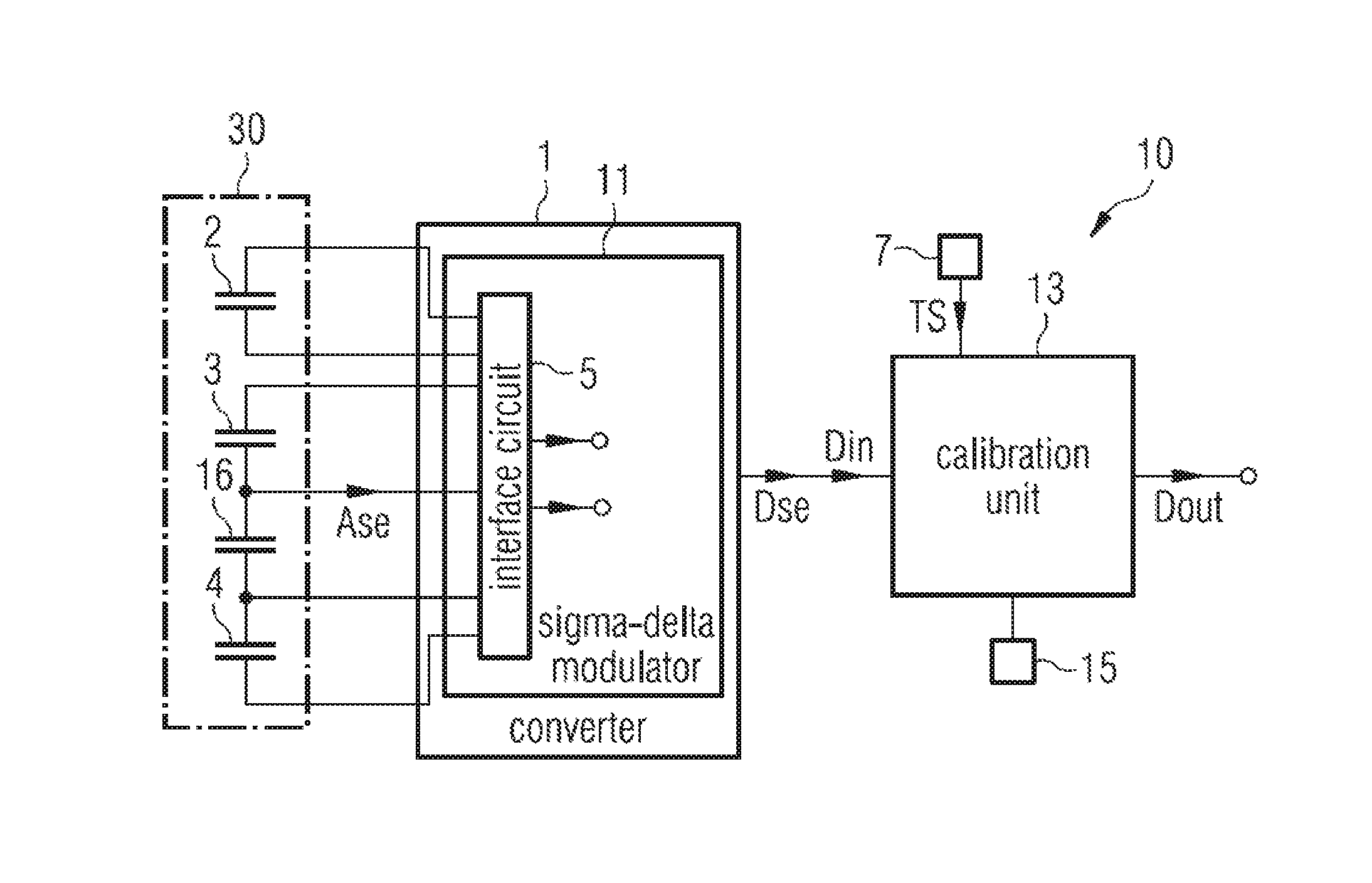
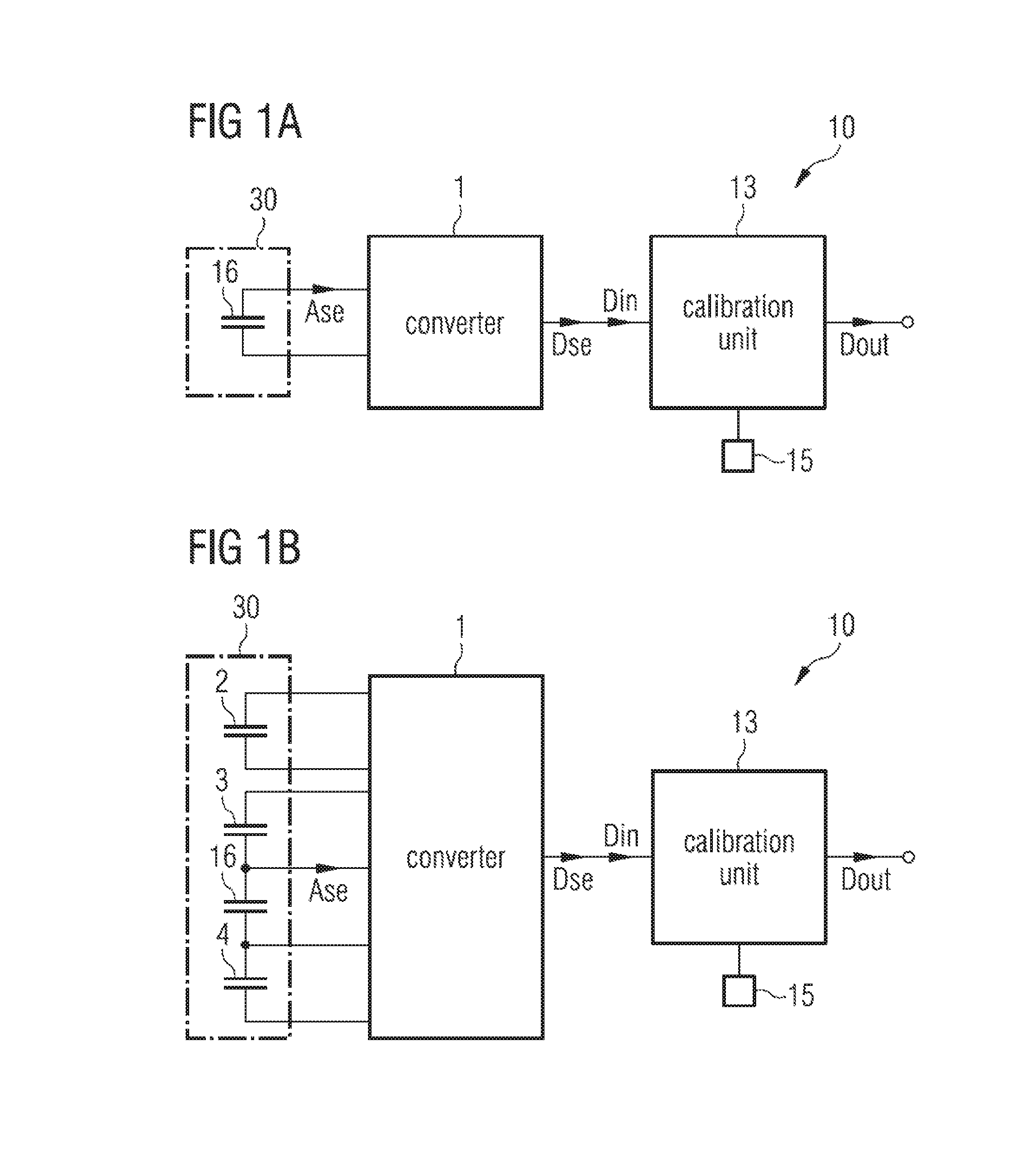
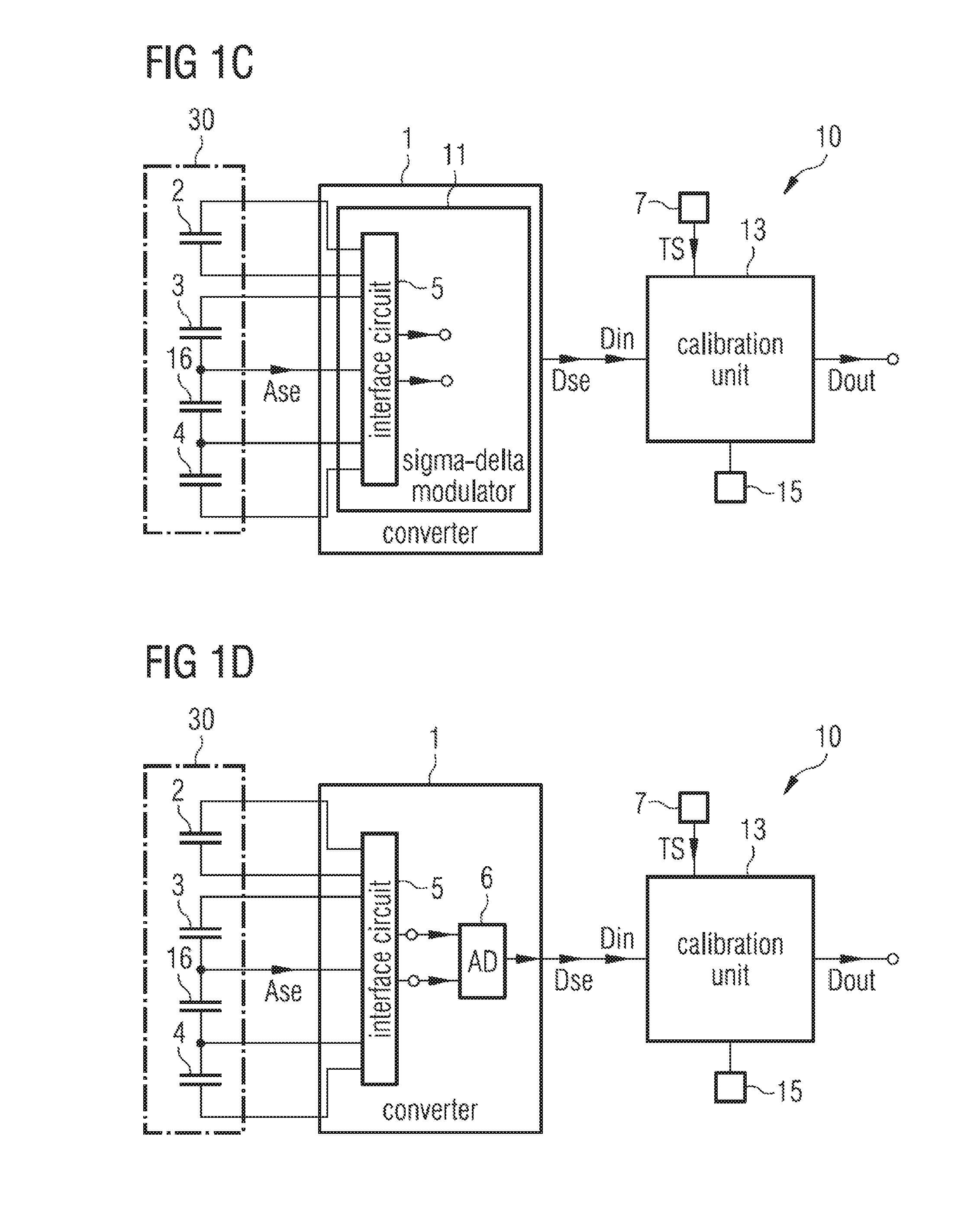
[0072]FIG. 1A shows an exemplary embodiment of a capacitance-to-digital converter 10, abbreviated CDC. The CDC 10 comprises a capacitor arrangement 30, a converter 1 and a calibration unit 13. An output of the capacitor arrangement 30 is coupled to an input of the converter 1. An output of the converter 1 is coupled to an input of the calibration unit 13. The capacitor arrangement 30 comprises an input capacitor 16. The input capacitor 16 is coupled to the converter 1. A memory 15 of the CDC 10 is coupled to the calibration unit 13.

[0073]An analog sensor signal Ase is provided by the input capacitor 16. The converter 1 generates a digital sensor signal Dse at its output. An input signal Din is provided to the input of the calibration unit 13. The input signal Din depends on the digital sensor signal Dse. The input signal Din may be equal to the digital sensor signal Dse. The calibration unit 13 generates a digital output signal Dout. The input signal Din is a digital signal.

[0074]Th...


PUM


Abstract

A capacitance-to-digital converter (10) comprises a capacitor arrangement (30), a converter (1) that is coupled on its input side to the capacitor arrangement (30) and a calibration unit (13) that is coupled on its input side to the converter (1). The capacitor arrangement (30) comprises an input capacitor (16).

Description

BACKGROUND OF THE INVENTION[0001]The present patent application is related to a capacitance-to-digital converter and to a method for providing a digital output signal.[0002]Capacitive sensors are used in many applications to measure chemical and physical parameters. In order to be accurate enough, the measurement of such parameters requires a high resolution and a low-noise capacitance-to-digital converter, abbreviated to CDC. Conventional CDCs generate an intermediate voltage which is then digitized by means of an analog-to-digital converter. In most applications, the power supply rejection ratio, abbreviated to PSRR, is an important parameter. Moreover, most of the capacitive sensors are single-ended. A characteristic such as a high PSRR and a high linearity cannot easily be achieved by a CDC.[0003]Document U.S. Pat. No. 8,410,969 B2 refers to a wide range charge balancing capacitive-to-digital converter. The CDC comprises a single-ended sensor, an offset capacitor, a reference ca...

Claims


Application Information

Patent Timeline
Patent Type & Authority Patents(United States)
IPC IPC(8): H03M1/06H03M1/10H03M1/12G01R27/26H03M3/00
CPCH03M1/1019H03M1/12H03M3/356H03M3/382H03M3/458G01R27/2605H03M3/34
Inventor GARCIA GONZALEZ, JOSE MANUELBERTOMEU MESTRE, JOELSERRANO GOTARREDONA, RAFAEL
Owner AMS AG
Why Eureka
Try Eureka