Method of converting 2D video to 3D video using 3D object models

a technology of object models and 2d video, applied in the field of image processing, can solve the problems of large amount of manual labor and expense in the conversion process, large time-consuming and labor-intensive conversion process, and noisy depth maps provided by external systems, and achieve the effect of rapid conversion of movies and increased artistic and technical flexibility

Inactive Publication Date: 2016-09-06
LEGEND FILMS INC
View PDF421 Cites 122 Cited by
  • Summary
  • Abstract
  • Description
  • Claims
  • Application Information

AI Technical Summary

Benefits of technology

[0013]One or more embodiments described in the specification are related to method of converting of 2D video to 3D video using 3D object models that provides increased artistic and technical flexibility and rapid conversion of movies for stereoscopic viewing. Embodiments of the invention convert a large set of highly granular depth information inherent in a depth map associated with a two-dimensional image to a smaller set of rotated planes associated with masked areas in the image. This enables the planes to be manipulated independently or as part of a group and eliminates many problems associated with importing external depth maps including minimization of errors that frequently exist in external depth maps
[0017]In addition, by transforming the Z-Depth into a manageable number of parts, the system enables an artist to group these parts and apply separate RGB image layers to these groups. This enables more efficient occlusion filling in the 2D to 3D conversion workflow.
[0024]Embodiments may also include grouping two or more of the planes in order to provide a piecewise masked surface area. The grouping may include a link of a predefined minimum and maximum distance, which enables moving one plane to move other grouped planes if the maximum values are hit. The minimum values may be zero or negative to allow to precise joining of planes or slight overlap for example. In one or more embodiments, the grouping may include a link having a spring constant, this enables the movement of planes relative to one another to self align with respect to the other planes to minimize the overall spring force on three or more of the corner points of the plane. Alternatively or in combination, embodiments of the invention may include altering automatically any combination of position, orientation, shape, depth or curve of said plane in order to fit edges or corners of the plane with another plane. This enables a plane to be positioned in three-dimensional space, rotated in three-dimensions, reshaped by moving a corner point, warped in effect by adding depth or a curve to the plane, for example to add depth to the plane itself to match the underlying image data. Embodiments of the invention may also include accepting an input to alter any combination of position, orientation, shape, depth or curve of the plane, for example to artistically fit the underlying image data, correct errors or artifacts from the automated fitting process for touch up, etc.
[0027]Conversion of 3D data to a 3D object model may for example include retopologizing the 3D data to a lower polygon count model or to a model with parameterized surfaces. One or more embodiments may use retopologizing techniques to reduce model complexity. Conversion may for example include fitting one or more planes to the 3D data and generating a 3D object model from these planes. Any of the techniques described above for fitting and adjusting planes or other surfaces may be used in one or more embodiments to generate a 3D object model. For example, one or more planes may be defined using regression fit, orthogonal distance regression fit, or calculation of normal vectors to the planes. One or more embodiments may combine multiple planes into groups of planes with links between the planes; links may for example define constraints between the edges or corners of the planes. One or more embodiments may employ link constraints that define maximum or minimum values for distances or angles. One or more embodiments may employ link constraints that use spring constants for the links and that for example minimize a potential energy of the model using the spring constants. One or more embodiments may define masks for selected areas of the model, using for example areas of predefined size or predefined depth, or areas with boundaries determined by changes in luminance or other image features over predefined thresholds.
[0029]One or more embodiments may locate and orient a 3D model in a frame using one or more model features. Features on the 3D object model may be aligned with pixel locations in the frame, and the 3D object model position and orientation in the 3D space of the scene may be calculated using techniques known in the art to minimize errors between observed pixel coordinates and the projection of the 3D feature points onto the image plane. One or more embodiments may align 3D object models with images in a frame in one or more key frames, and automatically determine the alignment in non-key frames using automated feature tracking

Problems solved by technology

Two-dimensional images however may include shading and lighting that provide the observer a sense of depth for portions of the image, however, this is not considered a three-dimensional view of an image.
Systems in this category may be automated to provide depth information based on colors or areas of the picture, but these systems have had limited success.
The main problems with this first category of conversion are time of conversion based on the large amount of manual labor and the expense of the conversion process.
However, there are many problems that occur when using an externally generated depth map to a Z-depth.
One of the main problems is that depth maps provided by external systems are noisy, may include inaccurate edges, spikes and spurious values, all of which are common with Z-depths generated from external systems.
Another problem is that since the depth maps correspond either on a pixel-by-pixel basis or at least generally fairly high resolution with the associated two-dimensional image, manipulating depth on this fine granularity is extremely difficult and time consuming.
Artifacts on edges of objects are common in some systems limiting their overall automation capabilities.
In addition, in many cases it is impractical to obtain externally generated depth information for every frame in a 2D video.
Technologies to generate 3D information, such as 3D scanners, are expensive and time-consuming to use.
However, this 3D information is static rather than integrated into each frame of a 2D video.
There are no known systems that take static 3D models of objects and propagate them across multiple frames of a 2D video to generate a 3D video.
There are no known systems that generate rigged 3D models from external depth information, and propagate these models across all frames of a 2D video scene.

Method used


Image

  • Method of converting 2D video to 3D video using 3D object models
  • Method of converting 2D video to 3D video using 3D object models
  • Method of converting 2D video to 3D video using 3D object models

Examples


Embodiment Construction

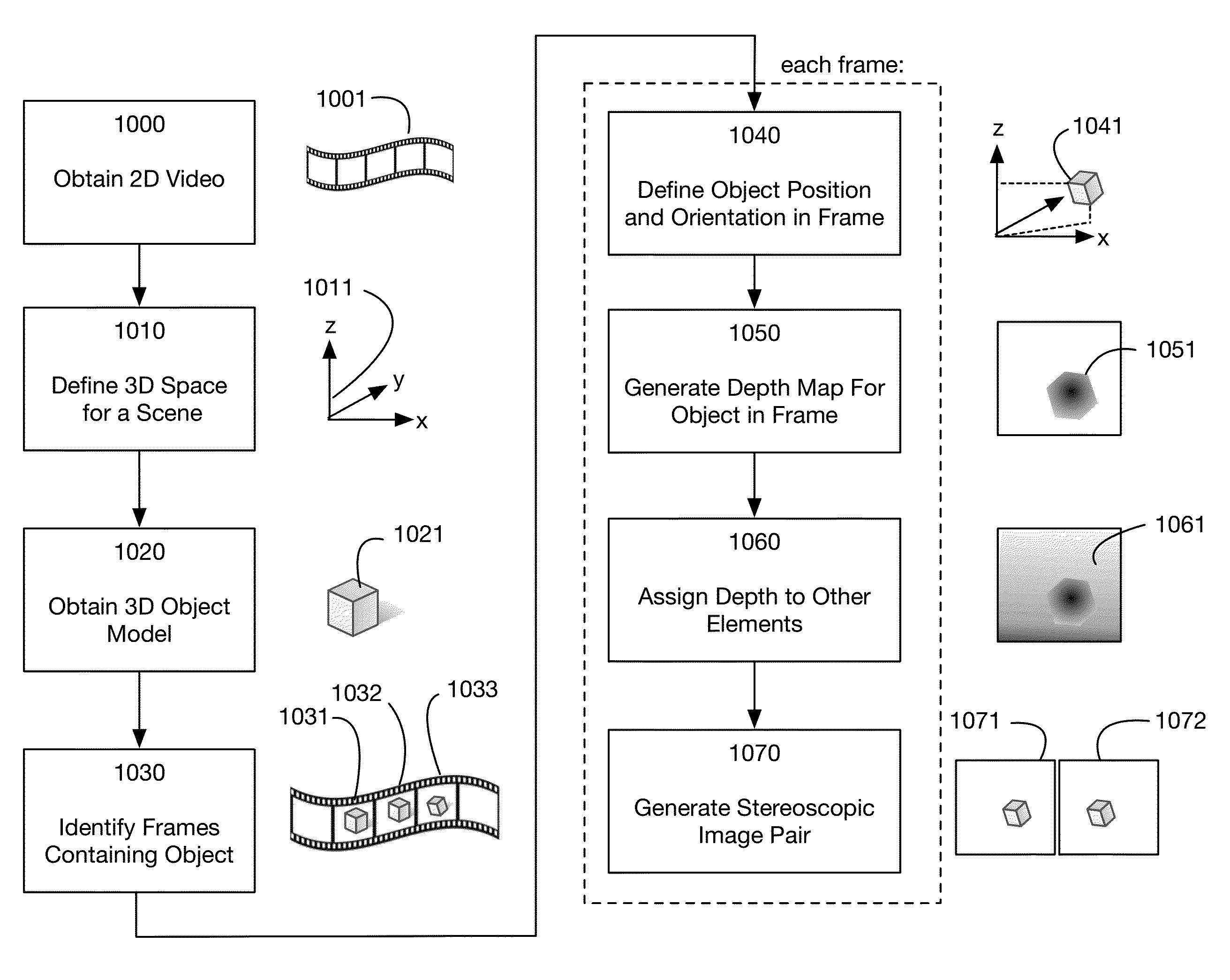
[0051]An method for converting 2D video to 3D video using 3D object models will now be described. In the following exemplary description numerous specific details are set forth in order to provide a more thorough understanding of embodiments of the invention. It will be apparent, however, to an artisan of ordinary skill that embodiments of the invention may be practiced without incorporating all aspects of the specific details described herein. In other instances, specific features, quantities, or measurements well known to those of ordinary skill in the art have not been described in detail so as not to obscure the invention. Readers should note that although examples of the invention are set forth herein, the claims, and the full scope of any equivalents, are what define the metes and bounds of the invention.

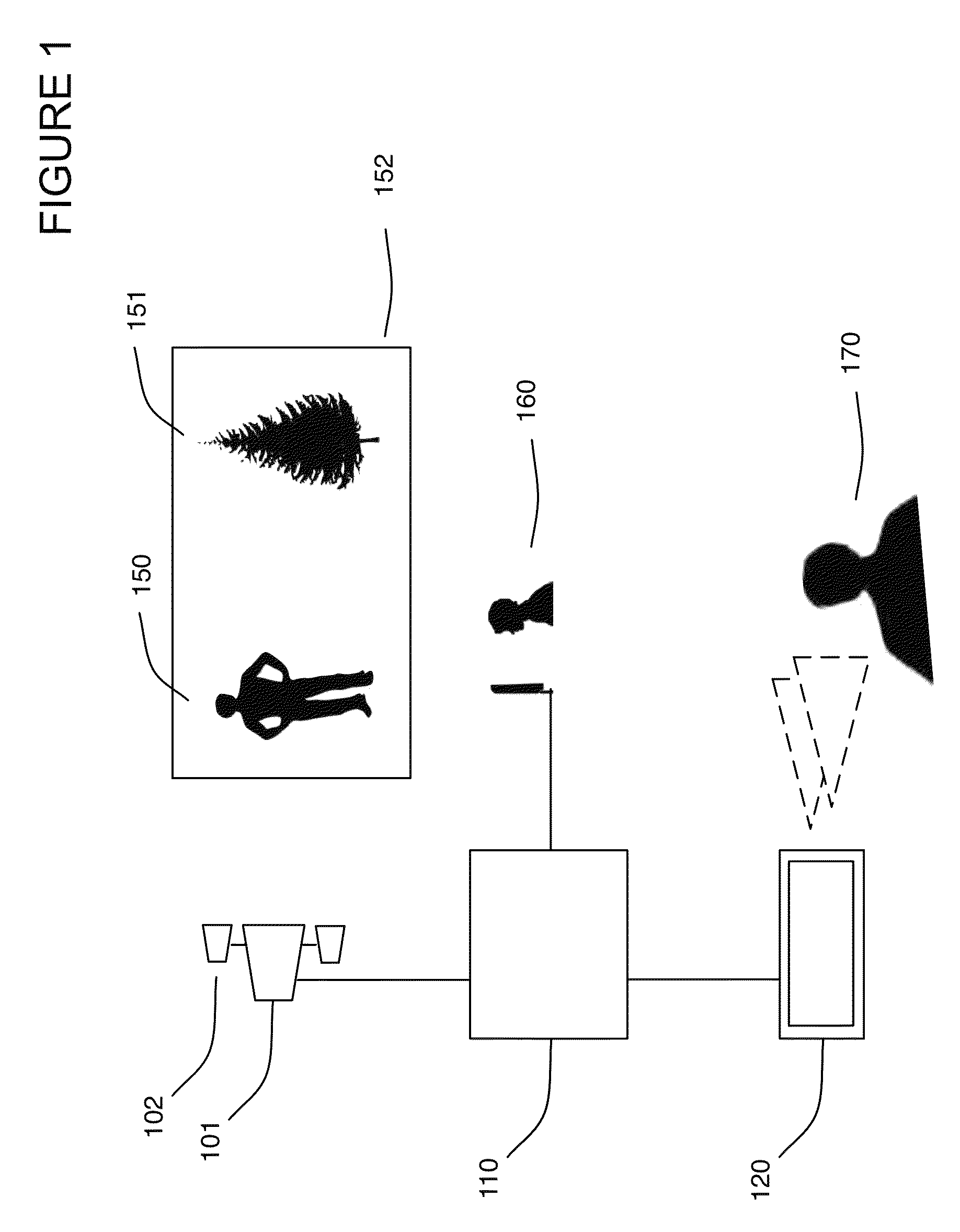
[0052]FIG. 1 illustrates an exemplary overall system architecture for one or more embodiments of the invention. As shown, camera 101 and associated external depth capture appa...


PUM


Abstract

Method for converting 2D video to 3D video using 3D object models. Embodiments of the invention obtain a 3D object model for one or more objects in a 2D video scene, such as a character. Object models may for example be derived from 3D scanner data; planes, polygons, or surfaces may be fit to this data to generate a 3D model. In each frame in which a modeled object appears, the location and orientation of the 3D model may be determined in the frame, and a depth map for the object may be generated from the model. 3D video may be generated using the depth map. Embodiments may use feature tracking to automatically determine object location and orientation. Embodiments may use rigged 3D models with degrees of freedom to model objects with parts that move relative to one another.

Description

[0001]This application is a continuation in part of U.S. Utility patent application Ser. No. 13 / 874,625, filed 1 May 2013, the specification of which is hereby incorporated herein by reference.BACKGROUND OF THE INVENTION[0002]1. Field of the Invention[0003]One or more embodiments of the invention are related to the image processing. More particularly, but not by way of limitation, one or more embodiments of the invention enable a method of converting 2D video to 3D video using 3D object models for one or more objects in the 2D video. Embodiments of the invention obtain 3D models of objects, such as characters, and process the frames of a video to locate and orient these models in the frames. Depth maps and stereoscopic 3D video may then be generated from the 3D models. Embodiments of the invention may convert 3D scanner data to a set of rotated planes associated with masked areas of the data, thus forming a 3D object model. This enables the planes to be manipulated independently or ...

Claims


Application Information

Patent Timeline
Patent Type & Authority Patents(United States)
IPC IPC(8): G06K9/00H04N13/00H04N13/02H04N13/128
CPCH04N13/0022H04N13/0018H04N13/026G06T7/557H04N13/122H04N13/128H04N13/261
Inventor NIEBLA, JR., VICENTEBALDRIDGE, TONYSCHAD, THOMASJONES, SCOTT
Owner LEGEND FILMS INC
Why Eureka
Try Eureka