Replacement cardiac valves and methods of use and manufacture

a technology valves, applied in the field of replacement cardiac valves, can solve the problems of obstructing blood flow, mitral stenosis, and insufficiency, and achieve the effects of reducing the risk of stroke, and improving the quality of li

Active Publication Date: 2016-09-13
CEPHEA VALVE TECH
View PDF594 Cites 130 Cited by
  • Summary
  • Abstract
  • Description
  • Claims
  • Application Information

AI Technical Summary

Problems solved by technology

These diseases can cause mitral stenosis, in which the valve fails to open fully and thereby obstructs blood flow, and / or mitral insufficiency, in which the mitral valve is incompetent and blood flows passively in the wrong direction.
Age or advanced illness may have impaired the patient's ability to recover from the injury of an open-heart procedure.
Additionally, the high costs are associated with open-heart surgery and extra-corporeal perfusion can make such procedures prohibitive.
Minimally invasive cardiac procedures are inherently less traumatic than open procedures and may be performed without extra-corporeal perfusion, which carries a significant risk of procedural complications.
However, current cardiac valve prostheses are not designed to function effectively within the mitral valve.
Further, current cardiac valve prostheses delivered via a minimally invasive device are often difficult to place correctly within the native valve, difficult to match in size to the native valve, and difficult to retrieve and replace if initially placed incorrectly.
Delivering a replacement valve transseptally imparts limitations on the size of the delivery device and the delivery profile of the replacement valve within the delivery device, and imparts certain flexibility requirements for the replacement valve itself as it is delivered transseptally to the location of the native mitral valve.
The inability to create an expandable anchor with varying thickness throughout can limit the functionality of different regions of the expandable anchor.
Certain regions of the expandable anchor may be limited in what they can be configured to perform by creating the valve from a single tubular element.
This can be undesirable if there is a need to create certain functionality in different regions of the expandable anchor that result from the regions have different thicknesses.
Furthermore, in a single-piece construction, strains are limited to the elastic strain limit of the material, which may be too low for some applications.

Method used


Image

  • Replacement cardiac valves and methods of use and manufacture
  • Replacement cardiac valves and methods of use and manufacture
  • Replacement cardiac valves and methods of use and manufacture

Examples


Embodiment Construction

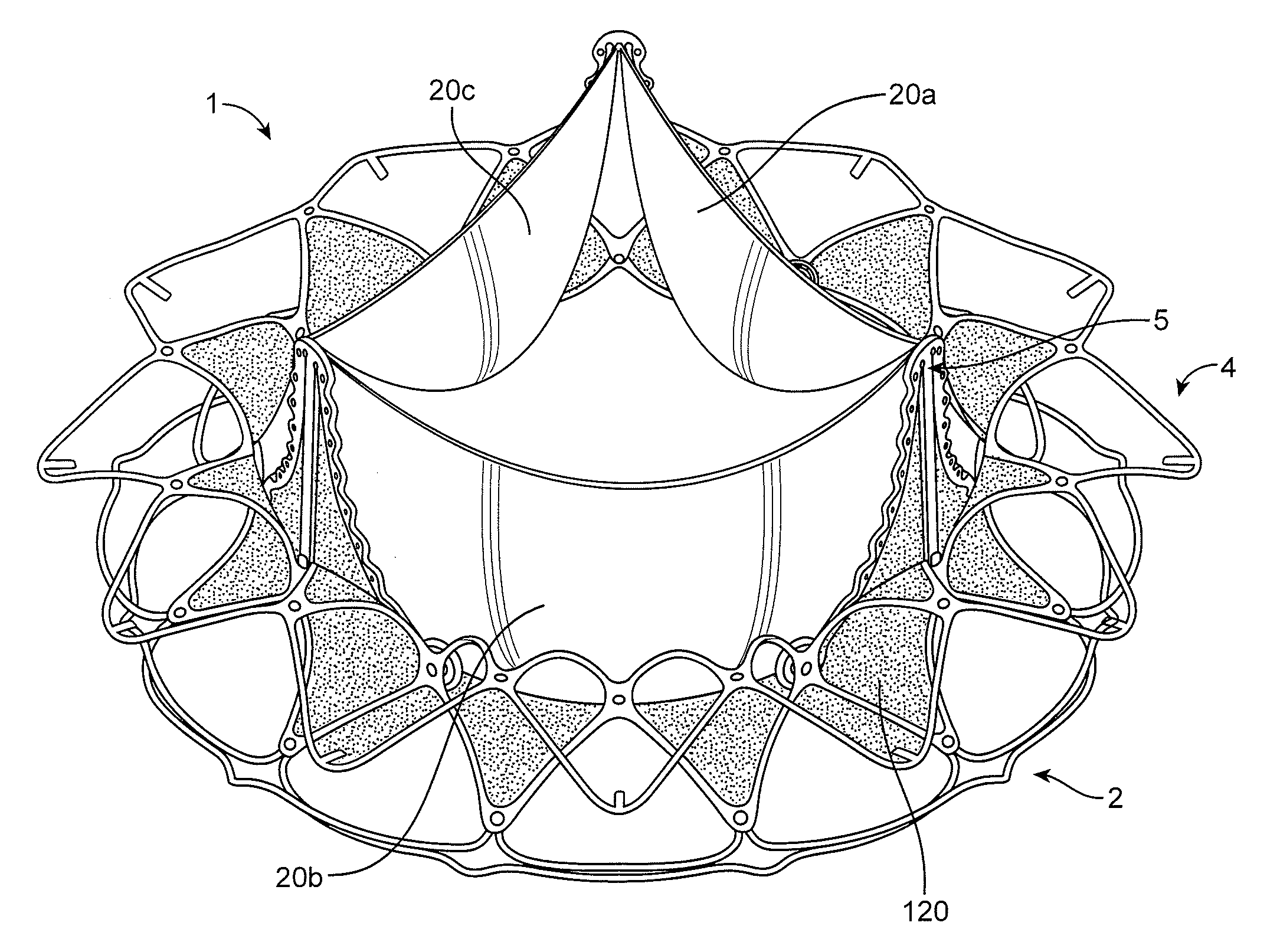
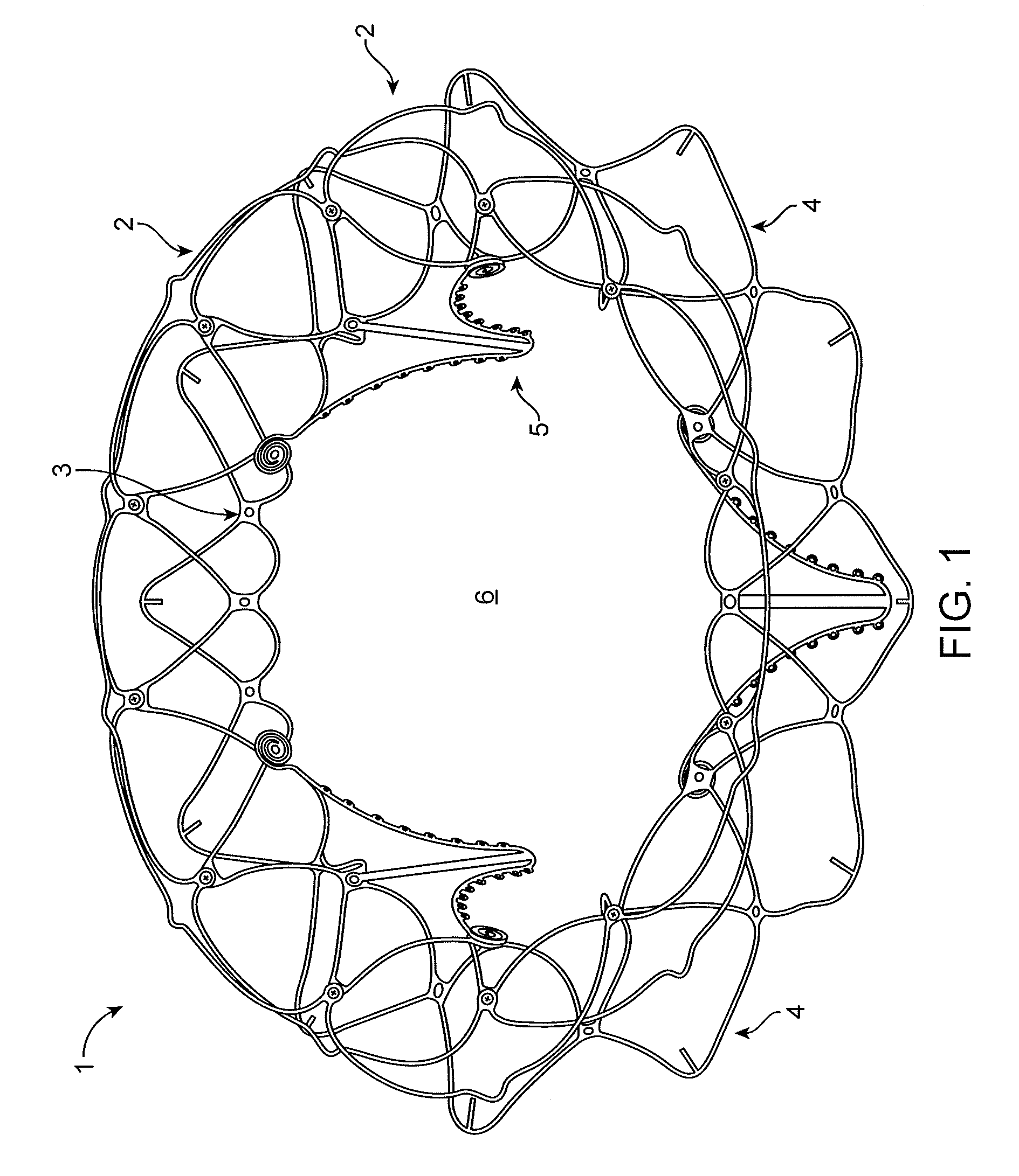
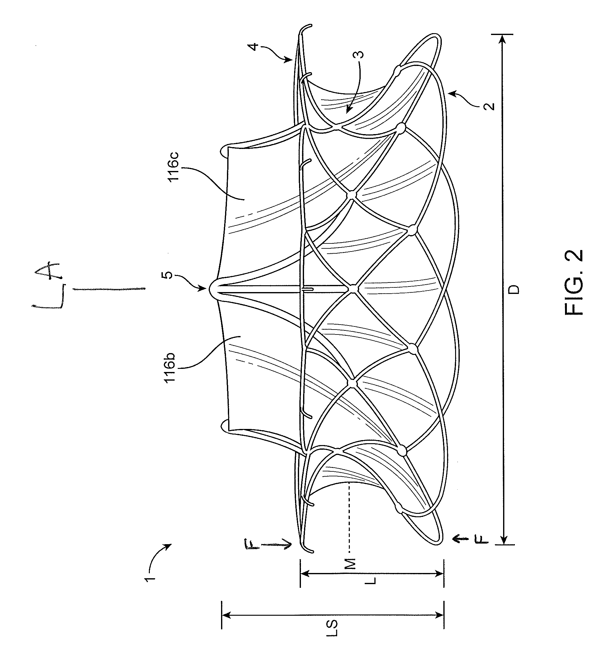
[0036]This disclosure includes replacement heart valves (also referred herein as prosthetic heart valves), methods of manufacturing replacement heart valves, including subassemblies thereof, and methods of using replacement heart valves. This disclosure describes the prostheses in the context of replacement mitral valves, but it is conceivable that the prostheses herein can be used or modified to be used as other replacement heart valves. In some embodiments the replacement heart valves are self-orienting (at least on one side) replacement mitral valves configured to be delivered using minimally invasive techniques.

[0037]The replacement heart valves herein include an expandable anchor that includes an atrial anchor (e.g., configured to be placed on an atrial side of a mitral valve annulus), a ventricular anchor (e.g., configured to be placed on a ventricular side of a mitral valve annulus), and a central portion axially between the atrial and ventricular anchors. The expandable anch...


PUM


Abstract

Prosthetic mitral valves and their methods of manufacture and use.

Description

CROSS REFERENCE TO RELATED APPLICATIONS[0001]This application claims priority to Provisional Application No. 62 / 089,719, filed Dec. 9, 2014, which is incorporated by reference herein.INCORPORATION BY REFERENCE[0002]All publications and patent applications mentioned in this specification are herein incorporated by reference to the same extent as if each individual publication or patent application was specifically and individually indicated to be incorporated by reference.BACKGROUND[0003]The mitral valve lies between the left atrium and the left ventricle of the heart. Various diseases can affect the function of the mitral valve, including degenerative mitral valve disease and mitral valve prolapse. These diseases can cause mitral stenosis, in which the valve fails to open fully and thereby obstructs blood flow, and / or mitral insufficiency, in which the mitral valve is incompetent and blood flows passively in the wrong direction.[0004]Many patients with heart disease, such as problem...

Claims


Application Information

Patent Timeline
Patent Type & Authority Patents(United States)
IPC IPC(8): A61F2/24
CPCA61F2/2409A61F2240/002A61F2210/0019A61F2/2418A61F2220/0041A61F2250/0063A61F2250/0018A61F2250/0036A61F2230/0006A61F2230/0069A61F2240/001A61F2/24A61B2017/00243A61F2/243
Inventor WALLACE, DANGROGAN, AARONNOE, SPENCERGREGG, PETER
Owner CEPHEA VALVE TECH
Why Eureka
Try Eureka