Apparatus for centrifugation and methods therefore

a centrifugation apparatus and centrifugation chamber technology, applied in centrifuges, separation processes, instruments, etc., can solve the problems of insufficient amount of blood collected in reservoirs for separation and wash procedures, insufficient viscosity of tissue samples, and insufficient amount of blood collected in reservoirs, so as to reduce the amount of medical waste and related costs, the effect of compromising the safety of samples

Active Publication Date: 2016-09-13
MICROAIRE SURGICAL INSTR
View PDF28 Cites 2 Cited by
  • Summary
  • Abstract
  • Description
  • Claims
  • Application Information

AI Technical Summary

Benefits of technology

[0044]The current invention solves many problems in cell separation by integrating the functions of being a suction canister and a centrifugation canister with density phase separation capability. A notable advantage of the present invention is the ability of the centrifuge canister to physically separate into two discrete non-contacting samples comprising a low density and a high density fraction. This complete separation enables mixing and harvest of the sample fractions without risk of intermingling of the density fluid layers.
[0045]Because of the heterogeneous nature of biological fluids, it is frequently difficult to transfer them from one container to another without causing unintended loss of material and increasing processing time. Further such fluid transfer can compromise the safety of the sample by introducing the risk of microbial contamination. Further, the amount of medical waste and related costs can be reduced by integrating different functions into a single device.
[0046]One object of the present invention is that the centrifuge vessel can be used as a suction canister for the harvest of biological fluids including blood, blood fractions, lipoaspirate, lipoaspirate fractions, bone marrow, and tissue fragments and combinations thereof. After centrifugal separation of the biological fluid, the centrifuge vessel geometry design enables a high and a low density fraction of the biological fluid to be harvested. By creating a centrifuge vessel integrating the functions of harvesting lipoaspirate by vacuum aspiration directly from the cannula used to probe the patient with the capability to centrifuge the same container and further designing a means for removal of a cell fraction formed by centrifugation, the present invention enables the quick and efficient preparation of lipoaspirate derived cellular compositions for therapeutic and cosmetic clinical applications at the point of care.
[0047]The dual use canister assembly consists of material composition to achieve a rigid container or to be a rigid container with a non-rigid container lining chamber for processing lipoaspirate. An example of a suitable rigid container material is polycarbonate. An example of a suitable non-rigid container inner lining material is polyvinyl chloride (PVC). The design and composition of the rigid container is such to withstand the implosive forces when its inner chamber has an air pressure less than atmospheric pressure so as to enable the collection of the lipoaspirate during lipoplasty. Further the design and composition of the rigid container is such that it will fit into a centrifuge bucket and withstand forces of centrifugation of at least 100×g for at least 5 minutes. Preferably, the canister can withstand forces of at least 2,000×g for 30 minutes. In the disclosed invention the canister is centrifuged for a sufficient period at a sufficient g-force to cause stratification of the lipoaspirate components into different fluid phase layers based upon differences in density of the fluid components. Further the design of the rigid container or the liner container supported by the rigid container enable the harvesting of one or more density phase layer formed during centrifugation. The said collected fraction is used for a therapeutic or cosmetic purpose.
[0048]In another embodiment, the suction canister is supplemented with an anticoagulant to prevent the formation of fibrin, which can potentially interfere with the harvesting step of the cellular components.

Problems solved by technology

The problems identified by Katz and Lull for processing lipoaspirate included the viscosity of the tissue sample being further increased by the oil released from cells damaged during the liposuction procedure or cell separation process.
They further noted the consistency of such liposuctioned tissue, particularly large samples of such tissue, causes occlusion of filtering mechanisms and is a significant hindrance to thorough, effective washing and cell separation.
Often the amount of blood collected in the reservoir is insufficient to carry out the separation and wash procedures.
This is wasteful and adds unnecessary expense to surgical procedures that ultimately do not lead to washing and reinfusing of blood to the patient.
A particularly important clinical problem is the lack of an effective means to wash away toxic cryopreservative agents present in thawed cell suspensions.
DMSO is such a toxic solvent commonly used for the cryopreservation of autologous peripheral blood stem cells, cord blood, and bone marrow.
None of the devices disclosed above adequately address the special processing concerns presented for concentrating viable cells from tissues for medical and veterinary therapeutic applications, diagnostic applications, cosmetic applications wherein simplicity, speed and reliability are highly valued.
Further, devices do not currently exist that have successfully addressed the technical challenges and operator needs in processing lipoaspirate where the range of volume is high (20 ml to 3 liters) and the fluid is particulate in nature.

Method used


Image

  • Apparatus for centrifugation and methods therefore
  • Apparatus for centrifugation and methods therefore
  • Apparatus for centrifugation and methods therefore

Examples


Embodiment Construction

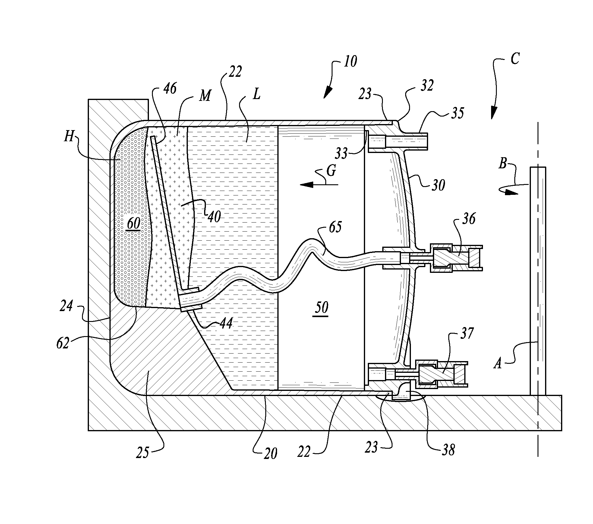
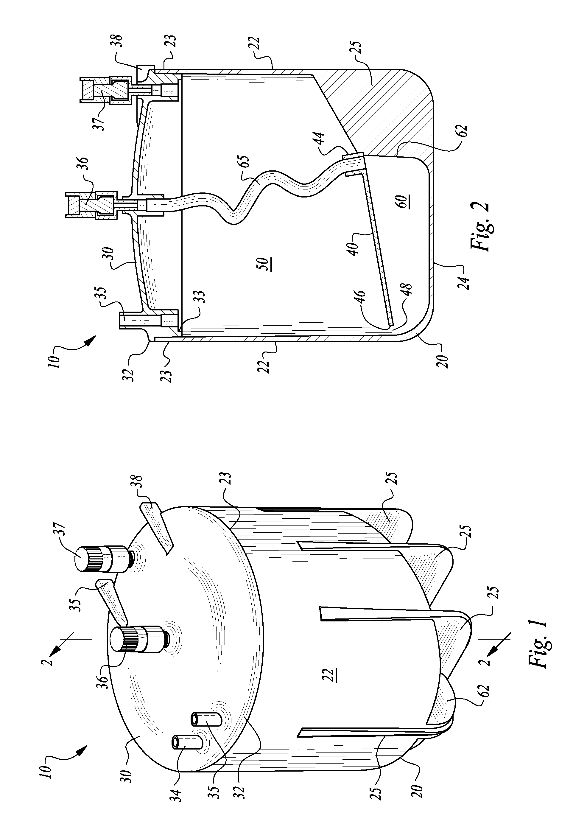
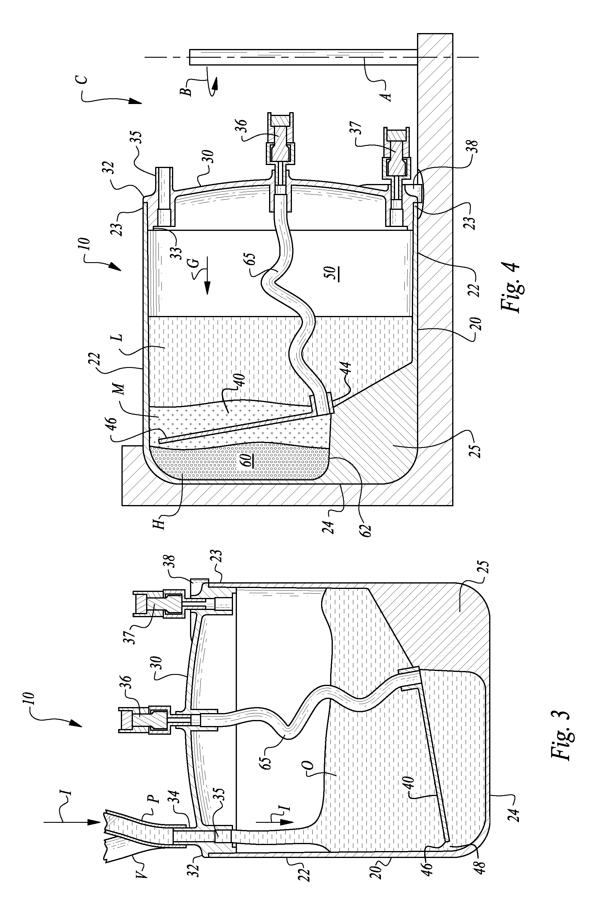
[0072]Referring to the drawings, wherein like reference numerals represent like parts throughout the various drawing figures, reference numeral 10 is directed to a centrifuge vessel, defining at least a portion of an apparatus according to one embodiment of this invention. The vessel 10 can be used to separate an original mixed density sample O into separate constituents having differing densities. The vessel 10 also is conveniently configured to keep the distinct constituents separate after centrifugation and to provide for convenient removal of separate constituents after centrifugation.

[0073]Any multi-constituent fluid sample having constituents of differing densities can be separated within the centrifugation vessel 10, with a specific example provided herein involving the separation of a biological fluid (e.g. lipoaspirate) into a high density phase (such as a cell pellet) from a low density phase (such as adipose tissue and / or other oils) and potentially also a medium density ...


PUM

PropertyMeasurementUnit
volumeaaaaaaaaaa
volumeaaaaaaaaaa
densityaaaaaaaaaa

Abstract

A centrifuge vessel is configured to have at least two chambers therein separated by a divider, and with a spillway around a lip at an end of the divider to join the chambers. After centrifugation differing density phases of an original sample remain on opposite sides of the divider. Separate extraction ports are provided for removal of differing density phases of the original sample from opposite sides of the divider. A method of use of the centrifuge vessel includes centrifugation and extraction at differing orientations of the vessel for convenient and reliable extraction of differing density fractions from the original sample.

Description

CROSS-REFERENCE TO RELATED APPLICATIONS[0001]This application claims benefit under Title 35, United States Code §119(e) of U.S. Provisional Patent Application No. 61 / 599,409 filed on Feb. 15, 2012 and U.S. Provisional Application No. 61 / 606,618 filed on Mar. 5, 2012.FIELD OF THE INVENTION[0002]This invention relates to apparatus and methods for the separation, concentration, collection and washing of density distinguishable constituents contained in a suspending fluid. The invention particularly relates to centrifuges, vessels and centrifuge operation methods which utilize sample containing vessel geometry to maintain separation of density phase layers after centrifugation and during harvest of density fractions. In some embodiments, the invention discloses a means to utilize or separately extract a medium density fluid to further facilitate separating the differing density fractions contained in a mother fluid.BACKGROUND OF THE INVENTION[0003]Essentially a centrifuge is an apparatu...

Claims


Application Information

Patent Timeline
Patent Type & Authority Patents(United States)
IPC IPC(8): B04B7/08B04B5/04G01N33/49A61M1/36A61M1/02
CPCB04B7/08A61M1/029A61M1/3693B04B5/0421B04B5/0442G01N33/491A61M2202/08
Inventor CHAPMAN, JOHN R.SPARKS, RODNEY
Owner MICROAIRE SURGICAL INSTR
Why Eureka
Try Eureka