Oxidation furnace

a technology of oxidation furnace and suction box, which is applied in the direction of furnaces, drying machines with progressive movements, lighting and heating apparatus, etc., can solve the problem that hot air no longer flows through the clearance between the suction box and the suction box, and achieve the effect of reducing construction

Active Publication Date: 2016-09-13
ONEJOON GMBH
View PDF12 Cites 4 Cited by
  • Summary
  • Abstract
  • Description
  • Claims
  • Application Information

AI Technical Summary

Benefits of technology

[0013]An object of the present invention is to design an oxidation furnace of the type mentioned at the outset so that a stipulated stretch of the oxidative treatment of the fibres can be accommodated in a relatively small volume of the furnace, and in particular the furnace can be of a lower construction.

Problems solved by technology

As a result, hot air no longer flows through the clearances between the suction boxes, at least not to any notable extent.

Method used


Image

  • Oxidation furnace
  • Oxidation furnace
  • Oxidation furnace

Examples


Embodiment Construction

[0026]While this invention is susceptible of embodiment in many different forms, there is shown in the drawings and will herein be described in detail one or more embodiments with the understanding that the present disclosure is to be considered as an exemplification of the principles of the invention and is not intended to limit the invention to the embodiments illustrated.

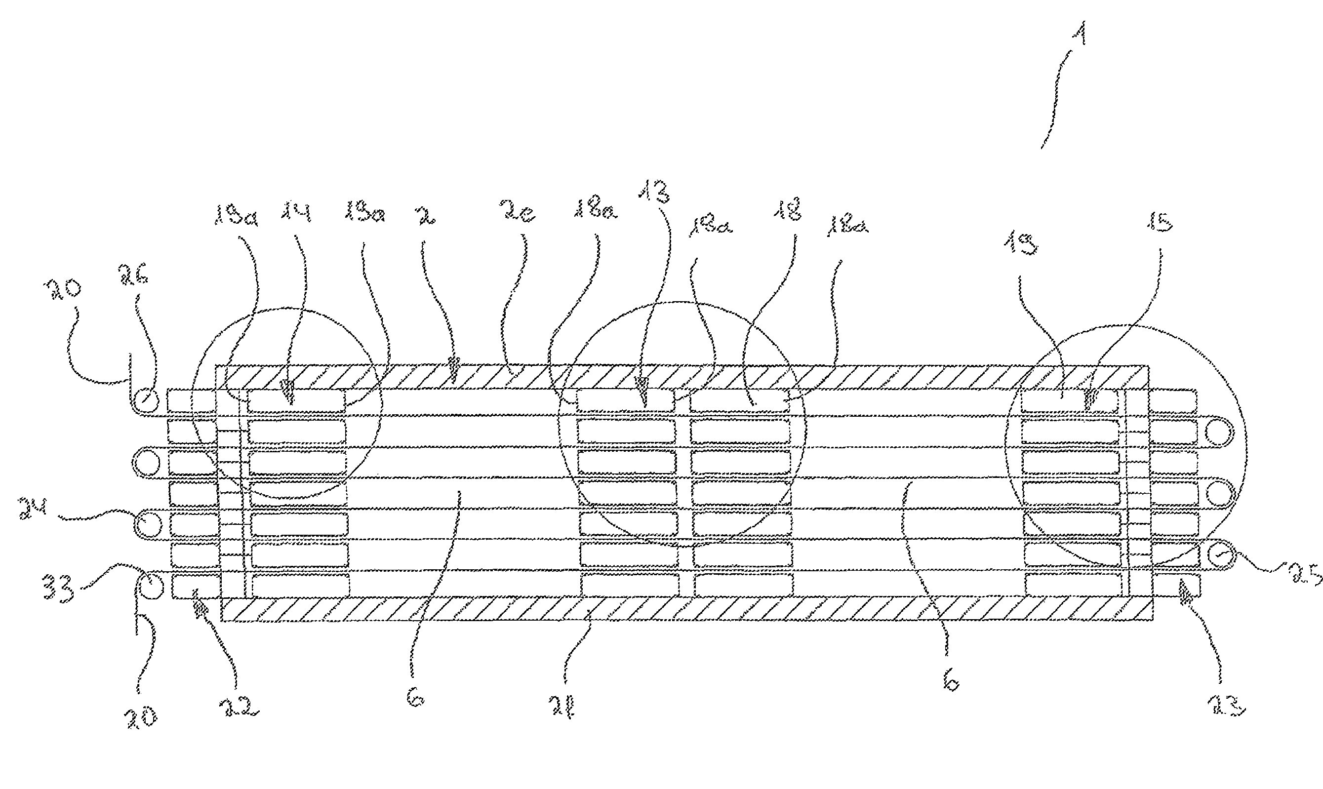
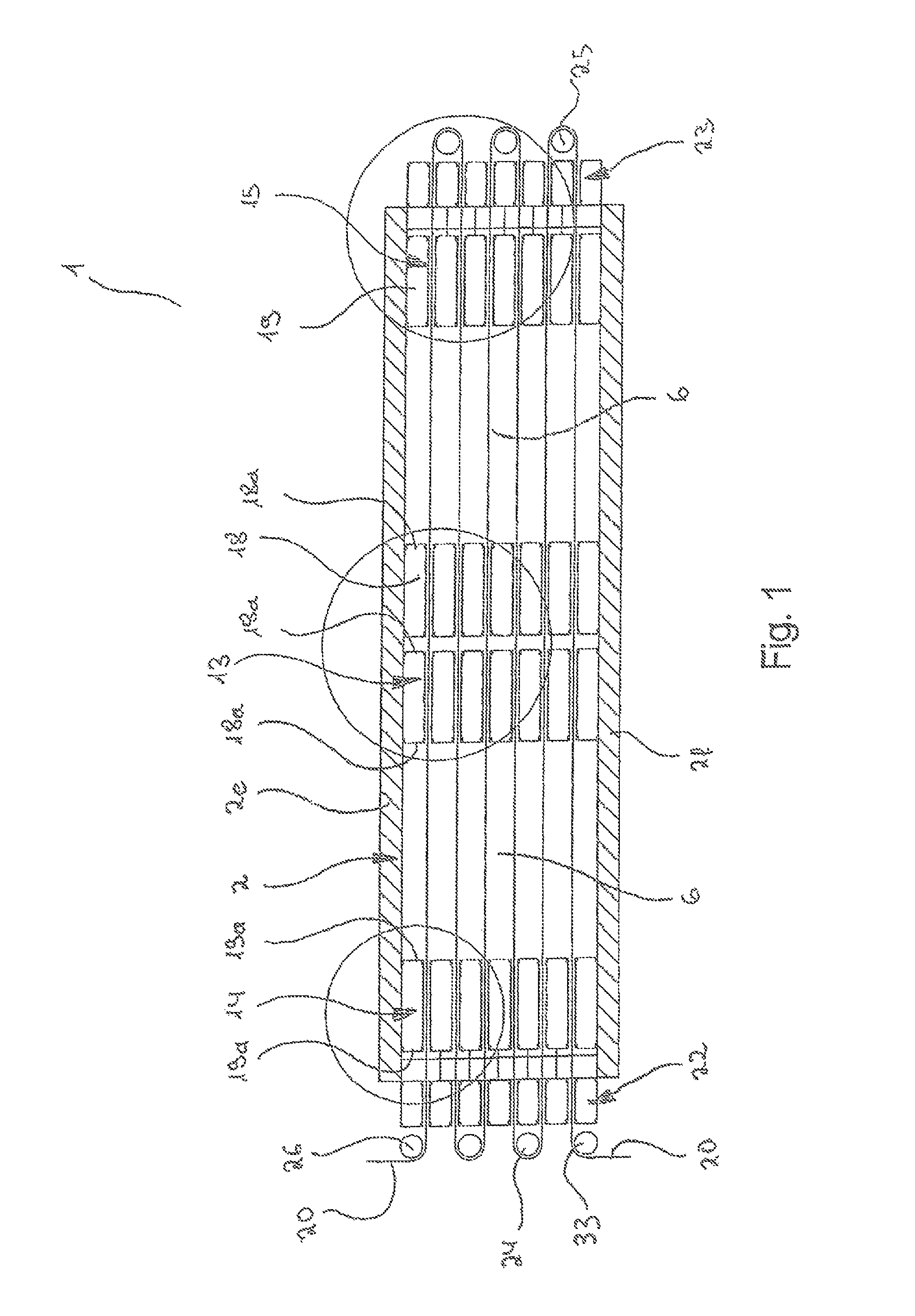
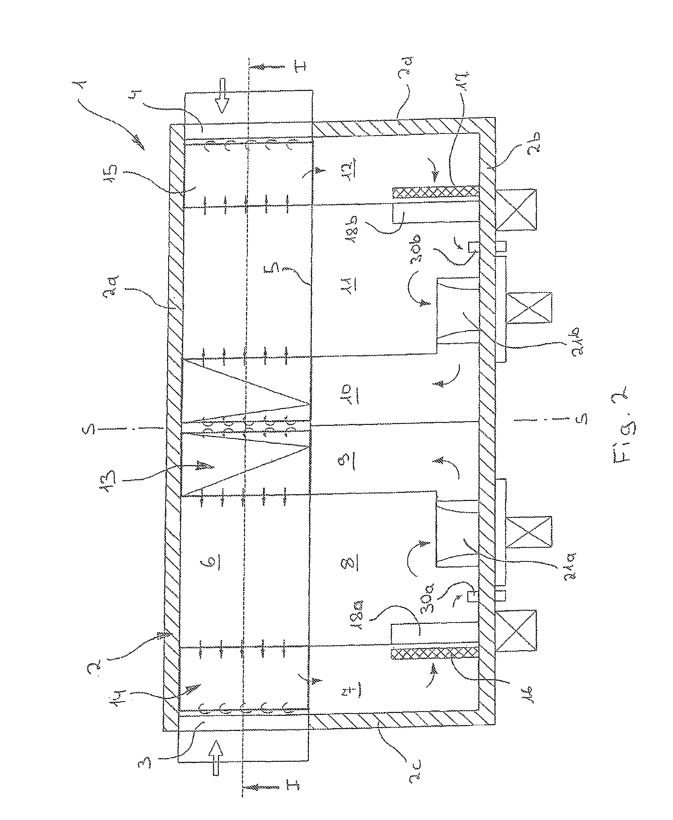
[0027]Reference is firstly made to FIGS. 1 to 3, which show an oxidation furnace which is denoted as a whole by the reference numeral 1 and is used to produce carbon fibres. The oxidation furnace 1 comprises a housing 2 which is in turn composed of two vertical side walls 2a, 2b, two vertical end walls 2c, 2d, a top wall 2e and a base wall 2f. The housing 2 is gastight with the exception of two regions 3, 4 in the end walls 2c and 2d, in which the fibres 20 to be treated are conducted in and out and which are provided with special lock devices 22.

[0028]As shown in particular in FIG. 2, the interior of the housing...


PUM

PropertyMeasurementUnit
air conductionaaaaaaaaaa
temperaturesaaaaaaaaaa
volumeaaaaaaaaaa

Abstract

An oxidation furnace for the oxidative treatment of fibers, especially for producing carbon fibers, which comprises a process chamber arranged inside a housing, a blowing device for hot air, at least one suction device arranged in an end region of the process chamber, at least one ventilator that circulates the hot air through the blowing device, the process chamber and the suction device, and at least one heating device arranged in the flow path of the hot circulated air. The suction device is formed from a plurality of vertically interspaced suction boxes. Said boxes have at least one outlet for the hot air, and at least one inlet for hot air, communicating with the process chamber and arranged in the outward-facing side of the suction boxes, that is the side that is at a distance from the center of the process chamber.

Description

RELATED APPLICATIONS[0001]This application claims the filing benefit of International Patent Application No. PCT / EP2011 / 000318, filed Jan. 26, 2011, which claims the filing benefit of German Patent Application No. 10 2010 007 481.0, filed Feb. 9, 2010, the contents of both of which are incorporated herein by reference.TECHNICAL FIELD AND BACKGROUND OF THE INVENTION[0002]The invention relates to an oxidation furnace for the oxidative treatment of fibres, particularly for producing carbon fibres, having[0003]a) a housing which is gastight apart from inlet and outlet regions for the fibres;[0004]b) a process chamber located in the interior of the housing;[0005]c) a blowing device by means of which hot air can be blown into the process chamber;[0006]d) at least one suction device which is arranged in an end region of the process chamber, extracts hot air from the process chamber and comprises a plurality of suction boxes which are arranged at a vertical spacing from one another and have...

Claims


Application Information

Patent Timeline
Patent Type & Authority Patents(United States)
IPC IPC(8): F27B9/28D01F9/32F26B13/00F26B13/08D02J13/00F26B21/02F26B23/02
CPCF26B13/005D01F9/32D02J13/001F26B13/08F26B21/02F26B23/022F27B9/28F27B9/3005F27D7/00
Inventor BERNER, KARL
Owner ONEJOON GMBH
Why Eureka
Try Eureka