
Head gimbal assembly (HGA) mounting apparatus for a magnetic head and disk tester

a technology of magnetic which is applied in the direction of magnetic recording, instruments, data recording, etc., can solve the problems of affecting accuracy and repeatability, affecting the performance of raising the cost of prior art collet assembly for head and disk tester, etc., to achieve the effect of improving performance and cost of manufactur

Active Publication Date: 2016-09-13
GUZIK TECHN ENTERPRISES
View PDF9 Cites 0 Cited by
  • Summary
  • Abstract
  • Description
  • Claims
  • Application Information

AI Technical Summary

Benefits of technology

This patent describes an improved mounting apparatus for a head gimbal assembly (HGA) and disk tester. The apparatus includes improved clamp fingers, a better compression structure, and a more rigid housing. These improvements prevent the issue of HGA base plate skewing and provide better positioning accuracy. The housing is made from a lightweight and cost-effective material. In summary, this patent presents a more efficient and cost-effective mounting apparatus for head and disk testers that provides improved performance.

Problems solved by technology

However, titanium is a costly material that raises the cost of prior art collet assemblies for head and disk testers as a whole.
Such a skewing disrupts correct positioning of the HGA, affects the accuracy and the repeatability of tester measurements, and can cause damage to the disk.
As a consequence, during movements of the air piston in such prior art collet assemblies, the unsecured end portion of the spreader pin bends during the movements of mounting an HGA.
Such bending results in radially directed movement of the upper end of the spreader pin, causing unwanted displacement of an HGA base plate to occur during placement into its test position on the tester.
A direct consequence of such a misplacement of an HGA, is test results which do not accurately reflect the true characteristics of the head of the HGA.
Thus, this diminishment of elasticity is one more factor leading to improper placement of an HGA for testing.
The above-mentioned disadvantages of known so-called collet assemblies for head and disk testers raise the cost for testing, and in some cases prevent the needed accuracy and reliability of testers.

Method used


Image

  • Head gimbal assembly (HGA) mounting apparatus for a magnetic head and disk tester
  • Head gimbal assembly (HGA) mounting apparatus for a magnetic head and disk tester
  • Head gimbal assembly (HGA) mounting apparatus for a magnetic head and disk tester

Examples


Embodiment Construction

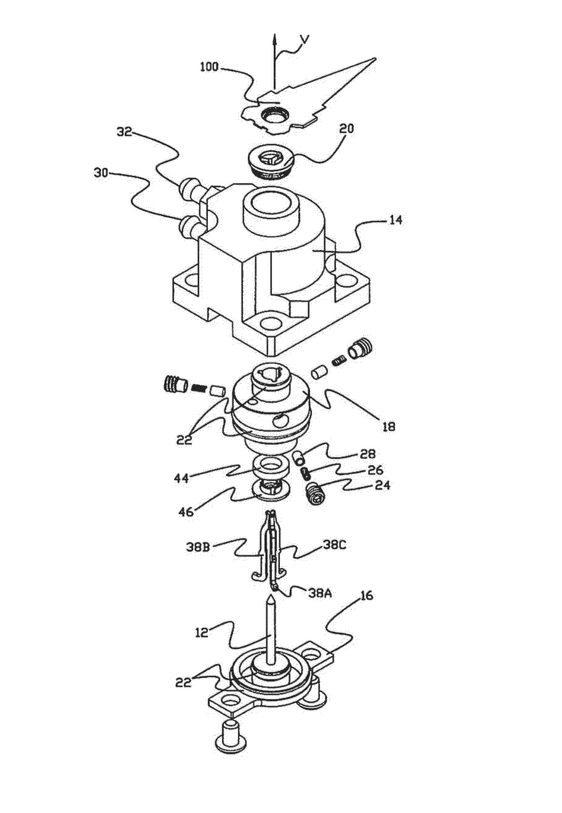
[0038]An exemplary head gimbal assembly (HGA) mounting apparatus 10 for a magnetic head and disk tester of the present disclosure, together with an exemplary HGA 100, is shown in FIGS. 3-6.

[0039]In the cross-section view of FIG. 3, the plane of the cross section does not pass through any of three clamp fingers 38A, 38B and 38C of mounting apparatus 10, and as a result, no clamp fingers are visible in FIG. 3. In the cross-section view of FIGS. 5-6, the plane of the cross section does pass through two of three clamp fingers of mounting apparatus 10, and as a result, those two clamp fingers 38A and 38B are visible in FIGS. 5-6. All three clamp fingers 38A, 38B and 38C of mounting apparatus 10 are visible in the exploded view of mounting apparatus 10 of FIG. 4.

[0040]In the exemplary form of mounting apparatus 10 shown in FIGS. 3-6, mounting apparatus 10 includes a two-element housing H comprising a housing base 14 and a stepped HGA supporting bushing 20, both disposed along and about a ...


PUM


Abstract

An apparatus for securing an HGA to a tester includes a housing with a cylindrical cavity disposed about an axis, and having, at its top end, a mounting surface with a central aperture, for receiving an HGA base plate with a boss hole of the HGA overlying the central aperture. Axially elongated clamp fingers, radially dispersed about a spreader pin, move along the axis between (i) a loading position with upper ends extending through and relatively far beyond the central aperture, and (ii) a clamping position with the upper ends disposed at or near the mounting surface. With an HGA on the mounting surface, and the clamp fingers at their loading position, the clamp fingers are driven downward, while simultaneously, the clamp fingers are driven outward by the spreader pin, and the clamp fingers engage boss hole edges, securing the HGA to the tester.

Description

REFERENCE TO RELATED APPLICATION[0001]This application claims priority to U.S. Provisional Patent Application Ser. No. 62 / 138,114, filed Mar. 25, 2015, incorporated by reference herein.FIELD OF THE INVENTION[0002]The present invention relates to magnetic head and disk testers, and in particular, to a device that mounts a read / write head on a head and disk tester.BACKGROUND OF THE INVENTION[0003]A magnetic head / disk tester is an instrument that is used for testing the characteristics of magnetic read / write heads and disks for various performance parameters, such as a signal-to-noise ratio, track profile, etc. A magnetic head / disk tester is operable to simulate motions of a head with respect to a disk that occur in an actual hard disk drive during operation. A tester comprises a mechanical component, commonly referred to as a spinstand, that performs movements of the head with respect to the disk, and an electronic component that is responsible for measurement, calculation, and analys...

Claims


Application Information

Patent Timeline
IPC IPC(8): G11B5/455G11B5/48
CPCG11B5/455G11B5/4826G11B5/4555G11B5/4813G11B19/048
Inventor GUZIK, NAHUMZHUANG, WEIPEREVOZTCHIKOV, KONSTANTIN
Owner GUZIK TECHN ENTERPRISES
Learn More