
Detection and correction of faulty photo controls in outdoor luminaires

a technology for outdoor luminaires and control devices, applied in the field of illumination, can solve the problems of consuming a significant amount of energy, compromising the flexibility of operation for ease of installation, and presenting higher efficiency light sources

Active Publication Date: 2016-09-13
EXPRESS IMAGING SYST
View PDF367 Cites 24 Cited by
  • Summary
  • Abstract
  • Description
  • Claims
  • Application Information

AI Technical Summary

Problems solved by technology

Such installations may however compromise operational flexibility for ease of installation and simplicity of operation.
Residential, commercial, and street lighting which illuminate interior and exterior spaces consume a significant amount of energy.
In some instances, these higher efficiency light sources may present a number of problems.
For example, fluorescent light sources may take a relatively long time after being turned ON to achieve their full rated level of output light or illumination.
Such light sources also typically have a high energy consumption during warm-up.
Low CRI light is less pleasing to the human eye.
Low CRI light makes it more difficult to discern details, often requiring a higher level of output light or illumination to discern details that would otherwise be discernable in high CRI light.
Automatic control devices such as photosensitive transducers (photosensors) and motion or proximity sensors add to the cost of a light fixture, and are frequently mounted in exposed positions where environmental or physical damage is unavoidable or vandalism may occur.
In addition, a failure of the automatic control mechanism, for example failure of a photosensor used to turn the light source ON or OFF dependent upon the measured ambient light level, may result in the light source remaining in a continuously ON state in the event the automatic control mechanism fails in a “closed” position, permitting current flow to the light source, or in a continuously OFF state in the event the automatic control mechanism fails in an “open” position, interrupting current flow to the light source.
Either failure mode results in an undesirable mode of operation of the light source.
A typical electro-mechanical relay used with a photocontrol for a luminaire has a relatively short life span.
Arcing caused by high capacitive in-rush currents of electronically ballasted luminaires and inductive “kick back” of magnetically ballasted luminaires can corrode the contactors of the electro-mechanical relays.
However, at relatively low voltages (e.g., 2V to 24V) and relatively low currents (e.g., microamps) such as those used for digital logic level signaling, the impedance presented by contaminants including oxide and sulfide accumulations can hinder or even prevent the transmission of current through the contactors.
Thus, conventional photocontrols for luminaires can have especially short life spans when used in applications where the switching of relatively low voltage and relatively low current signals is required, for example, with luminaires that include solid-state light source drivers, for example, light emitting diode (LED) drivers that receive control signals for LED arrays.
Due to the relatively short life span, photocontrols are a weak link in the reliability chain for illumination systems.
Often, service trips to replace a faulty photocontrol may cost significantly more than the photocontrol itself.

Method used


Image

  • Detection and correction of faulty photo controls in outdoor luminaires
  • Detection and correction of faulty photo controls in outdoor luminaires
  • Detection and correction of faulty photo controls in outdoor luminaires

Examples


Embodiment Construction

[0042]In the following description, certain specific details are set forth in order to provide a thorough understanding of various disclosed implementations. However, one skilled in the relevant art will recognize that implementations may be practiced without one or more of these specific details, or with other methods, components, materials, etc. In other instances, well-known structures associated with the various implementations have not been shown or described in detail to avoid unnecessarily obscuring descriptions of the implementations.

[0043]Unless the context requires otherwise, throughout the specification and claims that follow, the word “comprising” is synonymous with “including,” and is inclusive or open-ended (i.e., does not exclude additional, unrecited elements or method acts).

[0044]Reference throughout this specification to “one implementation” or “an implementation” means that a particular feature, structure or characteristic described in connection with the implemen...


PUM


Abstract

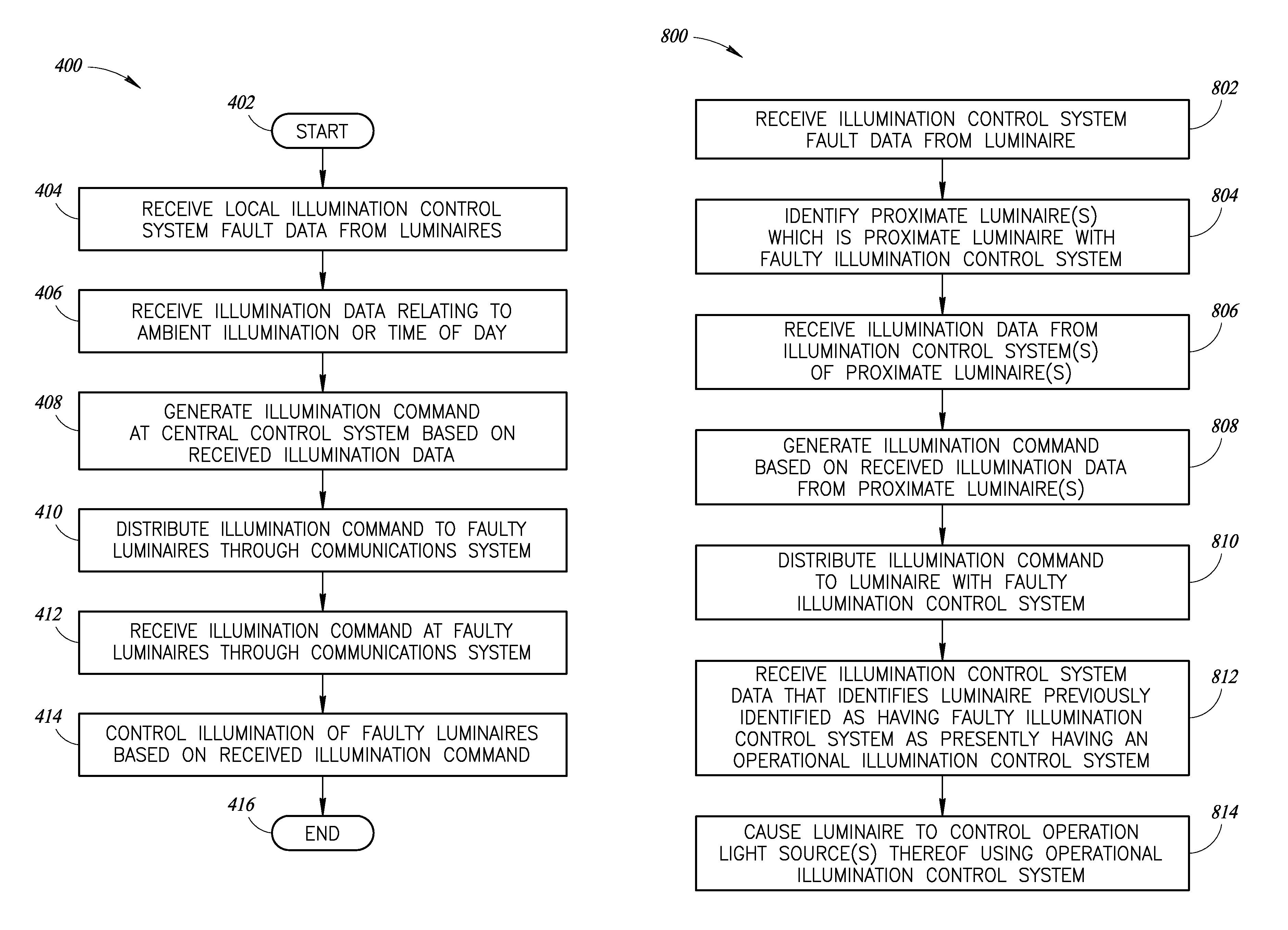
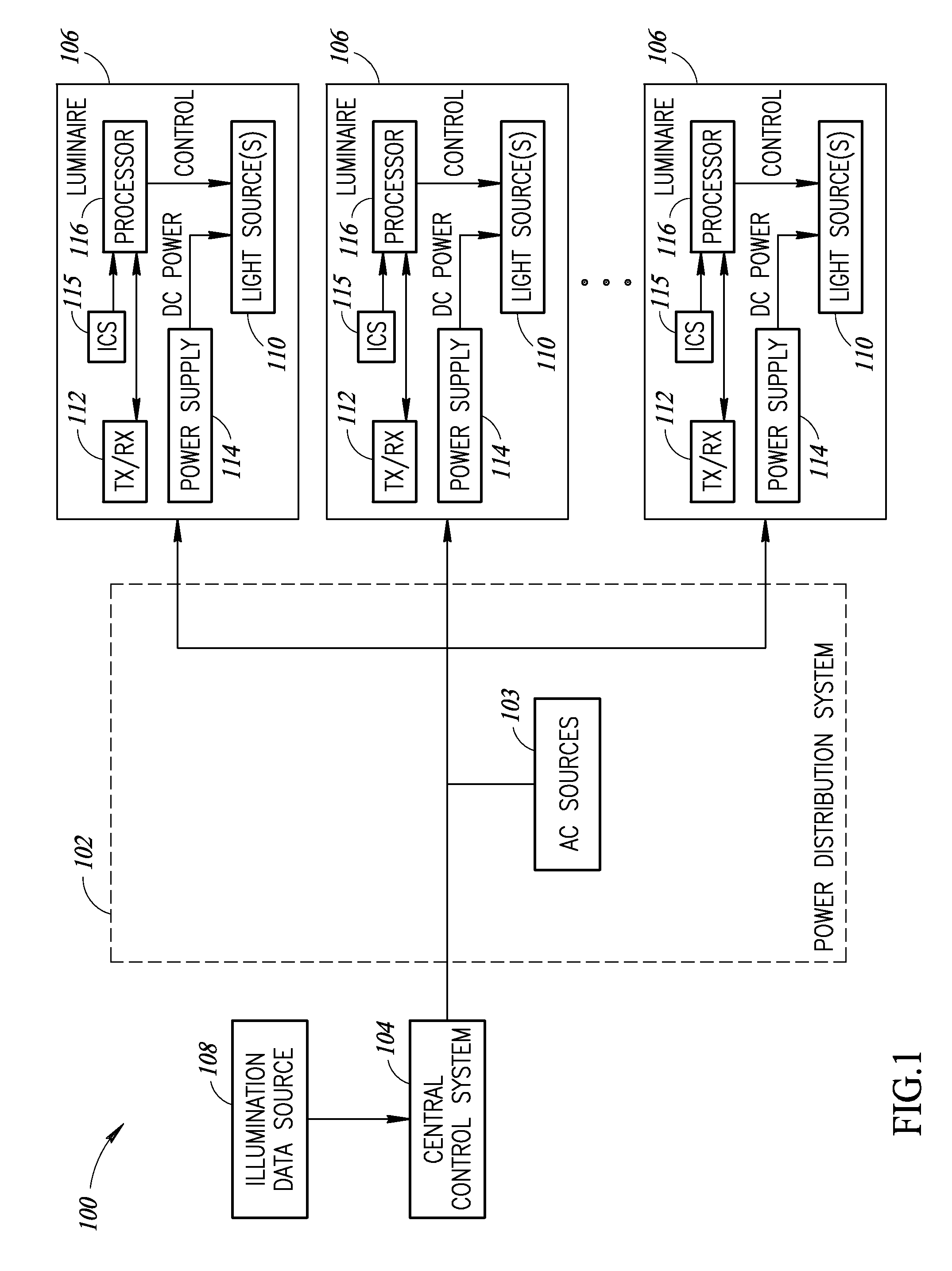
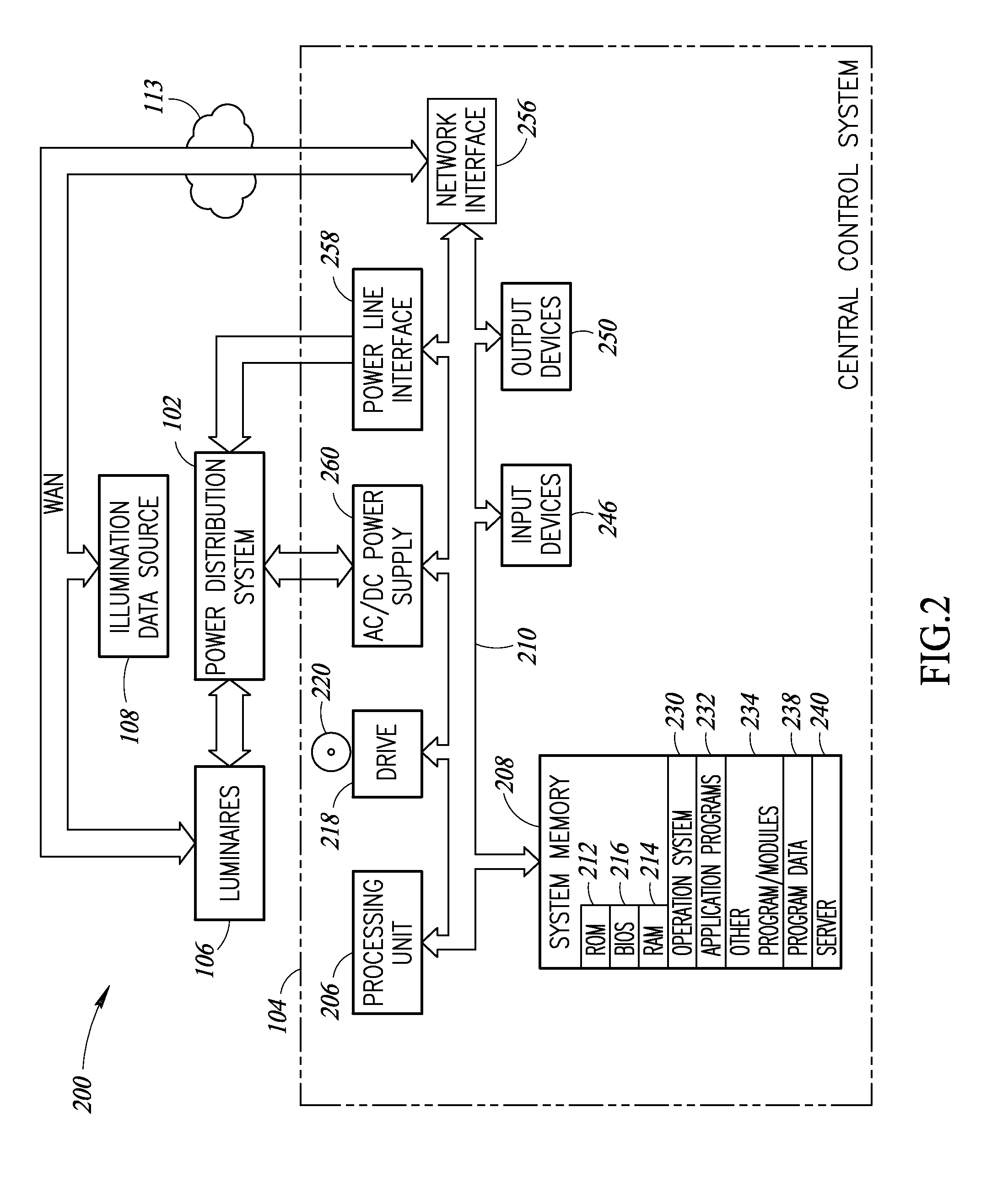
Systems, methods and articles for providing centralized control of area lighting hours of illumination. An area illumination system includes a central control system operatively coupled to a plurality of luminaires through a data communications network. In some implementations, the data communications network may include a power-line power distribution system and / or a wired or wireless communications network. Each of the plurality of luminaires includes a local illumination control system, which may include a photosensor. The central control system identifies one or more luminaires as having a faulty local illumination control system and issues illumination commands to such luminaires through the data communications network so that the luminaires continue to operate normally without a working local illumination control system. The central control system may store data relating to luminaires having faulty illumination control systems, such as addresses, map data, routing data, or the like.

Description

BACKGROUND[0001]1. Technical Field[0002]The present disclosure relates to illumination, and more particularly to control of a plurality of illumination devices and systems.[0003]2. Description of the Related Art[0004]Luminaires enjoy widespread use in a variety of industrial, commercial, and municipal applications. Such applications can include general or area lighting of workspaces, roadways, parking lots, and the like. Multiple luminaires are typically arranged in patterns and positioned at intervals sufficient to provide a minimum overall level of illumination across the area of interest. For example, luminaires may be spaced at intervals along a driveway in a multilevel parking garage to provide an overall level of illumination that permits safe ingress and egress by pedestrians as well as permits safe operation of motor vehicles within the parking garage. In a similar manner, luminaires may be spaced at intervals throughout a commercial center parking lot to promote safe operat...

Claims


Application Information

Patent Timeline
Patent Type & Authority Patents(United States)
IPC IPC(8): H05B37/02H05B37/03H05B41/36H05B39/04
CPCH05B37/03H05B37/0218H05B37/0254H05B37/0263H05B37/0272H05B37/0281H05B47/11H05B47/16H05B47/175H05B47/19H05B47/20H05B47/22Y02B20/40H05B47/18H05B47/185
Inventor REED, WILLIAM G.
Owner EXPRESS IMAGING SYST
Learn More