Vehicle door checker

a vehicle door and checker technology, applied in the field of vehicle door checkers, can solve the problems of deterioration, cracking of the reinforcing portion, separation, damage, etc., and achieve the effect of simple structur

Inactive Publication Date: 2016-09-20
RIKEN KAKI KOGYO CO LTD
View PDF20 Cites 2 Cited by
  • Summary
  • Abstract
  • Description
  • Claims
  • Application Information

AI Technical Summary

Benefits of technology

[0007]The present invention has been made with the foregoing situation taken into consideration. An object of the present invention is to provide a vehicle door checker capable of solving the above-mentioned problems with a simple structure.
[0009]According to the first aspect, the vehicle door checker is configured as follows. The check lever includes: the metal-made core plate extending in the longitudinal direction of the lever; and the synthetic resin-made covering portion integrally covering the core plate. The stopper surfaces provided to the support body are formed from: the pair of first stopper surfaces arranged side-by-side with the through-hole interposed therebetween; and the pair of second stopper surfaces arranged side-by-side with the through-hole interposed therebetween in the direction orthogonal to the arrangement direction of the first stopper surfaces. The pair of first stopper portions respectively engageable with the pair of first stopper surfaces are formed from the pair of metal-made protrusions provided projectingly and integrally on the opposite sides of the tip portion of the core plate, and projecting from the outer surface of the covering portion. In addition, the pair of second stopper portions respectively engageable with the pair of second stopper surfaces are formed from the pair of synthetic resin-made swelling portions which are portions of the outer surface of the covering portion located between the pair of first stopper portions and swollen on the one side and the opposite side, respectively, in the direction orthogonal to the arrangement direction of the first stopper portions. For these reasons, the pair of first stopper portions can be obtained by just projecting the parts of the metal-made core plate from the outer surface of the covering portion, and the pair of second stopper portions can be obtained by just swelling the parts of the synthetic resin-made covering portion. It is possible for the first and second stopper portions to receive load produced by opening the door such that the load is widely dispersed over the support body. Thereby, load burden on the stopper surfaces on the support body side can be reduced using a simple structure as a whole, and load burden on the synthetic resin-made second stopper portions can be reduced as well. Accordingly, it is possible to make great contribution to enhancement of durability of the various parts of the door checker.
[0011]According to the second aspect, the load produced by opening the door can be securely received mainly by engagement of the pair of metal-made first stopper portions with the pair of first stopper surfaces. In addition, even in a case where only one of the pair of first stopper portions is engaged with its corresponding first stopper surface due to partial contact, dispersion of the load produced by opening the door can be achieved by engaging the synthetic resin-made second stopper portions with the second stopper surfaces, since the support body is deformed in the first stopper surface with which the one first stopper portion is engaged due to the partial contact, and in the vicinity of the first stopper surface. For this reason, it is possible to make contribution to reducing load burden on the support body, thereby enhancing durability. Furthermore, contact surfaces of the second stopper portions with the second stopper surfaces each have a cross section with a convex arc shape. For this reason, surface contact of the second stopper portions with the second stopper surfaces is satisfactory so that stress on contact parts can be dispersed. Accordingly, it is possible to make contribution to further enhancing the durability of the synthetic resin-made second stopper portions.
[0013]According to the third aspect, when the door reaches an opening limit, proper engagement of the pair of first stopper portions with the pair of first stopper surfaces while in parallel with each other is achieved by: first of all, engaging the synthetic resin-made second stopper portions with the second stopper surfaces; and thereafter engaging the metal-made first stopper portions with the first stopper surfaces. For this reason, impact caused by their engagement can be effectively eased and absorbed by elastic deformation of the second stopper portions which occurs first, and occurrence of impact noise can be effectively prevented. In addition, since the metal-made first stopper portions are engaged with the first stopper surfaces, it is possible to securely avoid excessive elastic deformation of the synthetic resin-made second stopper portions. Furthermore, the contact surfaces of the second stopper portions with the second stopper surfaces each have the cross section with the convex arc shape. For this reason, the surface contact of the second stopper portions with the second stopper surfaces is satisfactory so that the stress on the contact parts can be dispersed. Accordingly, it is possible to make contribution to further enhancing the durability of the synthetic resin-made second stopper portions.
[0015]According to the fourth aspect, the pair of synthetic resin-made second stopper portions placed respectively on opposite sides of the metal-made core plate can be integrally connected together by the synthetic resin material which is filled and buried in the anchor hole in the tip portion of the core plate. For this reason, even if the load produced by opening the door is repeatedly applied to the second stopper portions, it is possible to effectively prevent each second stopper portion from coming off the core plate.
[0017]According to the fifth aspect, the rubber cover integrally including the pair of rubber covering portions is attached to the tip portion of the check lever, the pair of rubber covering portions covering the surfaces of the pair of second stopper portions which face the second stopper surfaces. The surfaces of the rubber covering portions, which face the second stopper surfaces, project, by the predetermined amount, toward the second stopper surfaces from the imaginary plane passing through the surfaces of the pair of first stopper portions which face the first stopper surfaces. Therefore, when the door is opened, the rubber covering portions of the rubber cover shock-absorbingly abut against the second stopper surfaces immediately before the opening limit of the door which is restricted by engagement of the first and second stopper portions with the first and second stopper surfaces. Thereby, the rubber covering portions are capable of effectively absorbing and easing impact which is caused when the door reaches the opening limit. Accordingly, the shock-absorbing effect can enhance the durability of the synthetic resin-made second stopper portions and the support body, and can effectively reduce impact load on the door supporting the support body, and the vehicle body. Moreover, since the through hole or the cutout through which the surfaces of the pair of first stopper portions facing the first stopper surfaces are exposed to the outside is formed in the rubber cover, it is possible to securely restrict the opening limit of the door by engaging the metal-made first stopper portions directly with the first stopper surfaces with no rubber cover interposed therebetween, and to effectively prevent damage of the rubber cover due to the engagement.

Problems solved by technology

Thus, the resin stopper portions may be cracked, separated, damaged, relatively early deteriorated, and so on, by impact at the time of engagement of the resin stopper portions with the stopper surfaces, particularly by impact at the time when the door is vigorously opened due to being hit by a gust of wind or due to for any other reason.

Method used


Image

  • Vehicle door checker
  • Vehicle door checker
  • Vehicle door checker

Examples


first embodiment

[0030]Descriptions will be hereinbelow provided for embodiments of the present invention on the basis of the accompanying drawings. To begin with, a first embodiment will be described with reference to FIGS. 1 to 7.

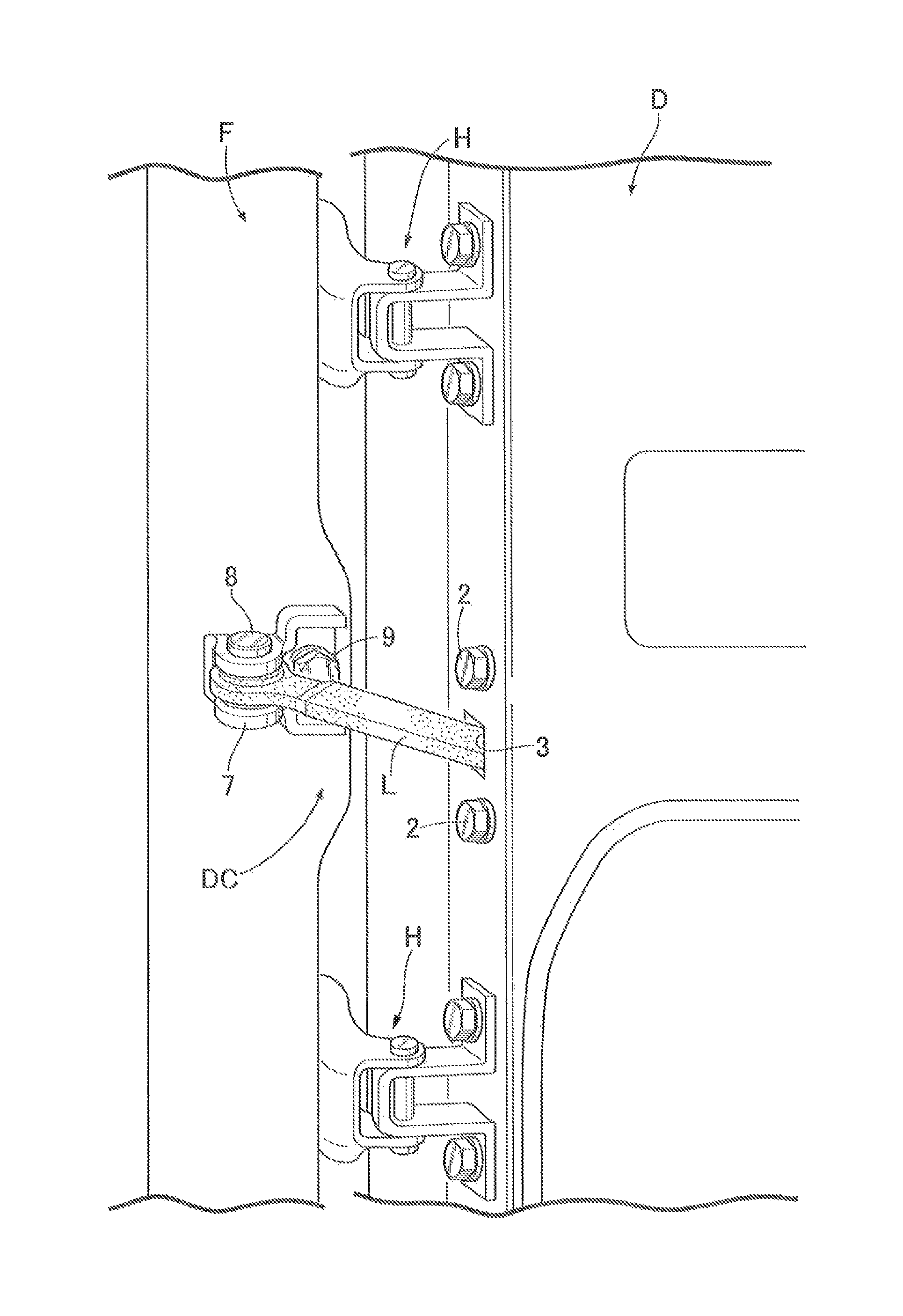
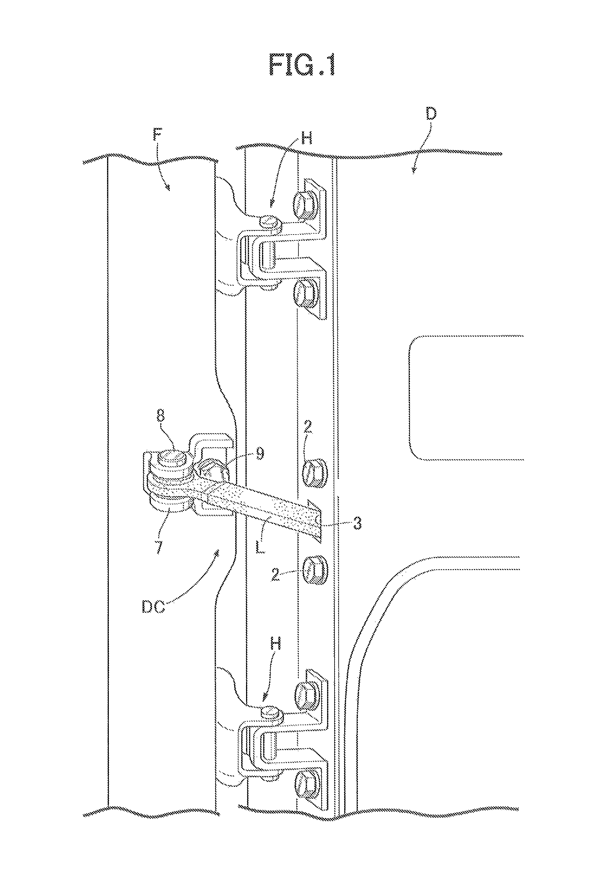
[0031]First of all, descriptions will be provided for an overall structure of a door checker. In FIG. 1, a door D for opening and closing an entrance is rotatably attached to a vehicle body F of an automobile via hinges H, and the door checker DC is attached between the vehicle body F and the door D.

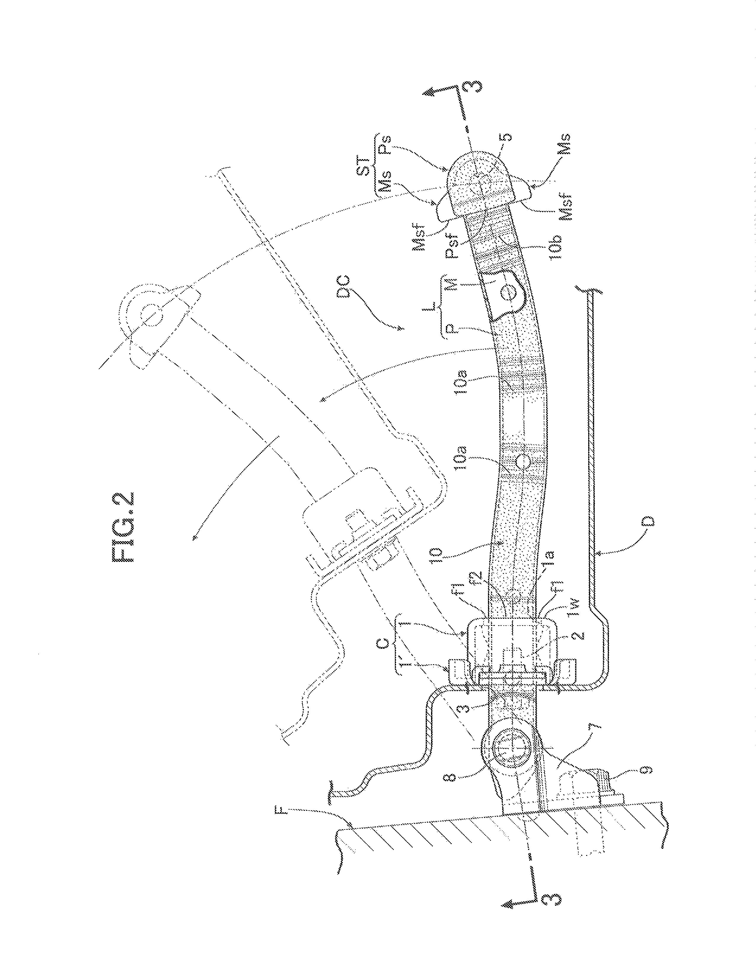
[0032]As shown in FIGS. 2 to 6, the door checker DC includes a case C fixedly attached to an inner surface of an end wall of the door D. The case C is formed from: a case body 1 as a support body, having a box shape with one end opened, and obtained by press-forming a metal plate such as a steel plate or the like; and a cover 1′ made of a metal plate such as a steel plate or the like, and connected to the case body 1 while covering the opened end of the case body 1. While abut...

second embodiment

[0053]For this reason, in the second embodiment, in a case where when the door D reaches the predetermined full-open position, as shown in FIG. 8A, the full-open stopper ST of the check lever L is engaged with the stopper surfaces f1, f2 of the case body 1 in the proper contact posture, first of all, the pair of metal-made protrusions Ms (the first stopper portions) are engaged with the pair of the first stopper surfaces f1. When the case body 1 is deformed due to impact caused by the engagement, and the first stopper surfaces f1 are slightly set back, the pair of synthetic resin-made swelling portions Ps (the second stopper portions) are engaged with the second stopper surfaces f2. Thereby, the load produced by opening the door can be securely received mainly by engagement of the metal-made protrusions Ms (the first stopper portions) with the pair of first stopper surfaces f1, and load burden on the pair of synthetic resin-made swelling portions Ps (the second stopper portions) can...

third embodiment

[0056]For this reason, in the third embodiment, in a case where when the door D reaches the predetermined full-open position, as shown in FIG. 9A, the full-open stopper ST of the check lever L is engaged with the stopper surfaces f1, f2 of the case body 1 in the proper contact posture, first of all, the pair of synthetic resin-made swelling portions Ps (the second stopper portions) are engaged with the second stopper surfaces f2. After the engagement, as shown in FIG. 9B, the pair of metal-made protrusions Ms (the first stopper portions) are engaged with the pair of the first stopper surfaces f1.

[0057]Thereby, at the opening limit of the door D, when the full-open stopper ST is engaged with the stopper surfaces f1, f2, first of all, impact caused by the engagement is effectively absorbed and eased by elastic deformation of the pair of synthetic resin-made swelling portions Ps (the second stopper portions). Thereafter, the pair of metal-made protrusions Ms (the first stopper portions...


PUM


Abstract

A door checker includes a stopper provided to a tip portion of a check lever and defining a door opening limit by engaging with stopper surfaces provided to an outer surface of a peripheral edge of a through-hole in a support body. The stopper is formed from paired first stopper portions engageable with paired first stopper surfaces arranged side-by-side with the through-hole therebetween, and paired second stopper portions engageable with paired second stopper surfaces. The first stopper portions are formed from metal-made protrusions integrally projecting from opposite sides of a tip portion of a lever core plate, and projecting from an outer surface of a synthetic resin-made covering portion. The second stopper portions are formed from synthetic resin-made portions of the outer surface located between the first stopper portions and swollen on opposite sides in a direction orthogonal to an arrangement direction of the first stopper portions.

Description

CROSS REFERENCE TO RELATED APPLICATIONS[0001]The present application claims priority under 35 U.S.C. §119 to Japanese Patent Application No. 2014-152286 filed Jul. 25, 2014 the entire contents of which are hereby incorporated by reference.BACKGROUND OF THE INVENTION[0002]1. Field of the Invention[0003]The present invention relates to an improvement of a vehicle door checker comprising: a check lever having a base portion pivotally supported by one of a vehicle body and a door; a support body made of a metal plate, including a through-hole for slidable insertion of the check lever therethrough, and fixedly attached to the other of the vehicle body and the door; and a stopper provided to a tip portion of the check lever and defining an opening limit of the door by engaging with stopper surfaces provided to an outer surface of a peripheral edge of the through-hole in the support body, especially, relates to an improvement of the vehicle door checker, wherein the check lever includes a ...

Claims


Application Information

Patent Timeline
Patent Type & Authority Patents(United States)
IPC IPC(8): E05F5/06B60J5/00
CPCE05F5/06B60J5/00Y10T16/615E05C17/206
Inventor MURAYAMA, YUJIASAKURA, JUN
Owner RIKEN KAKI KOGYO CO LTD
Why Eureka
Try Eureka