
Adjusting mechanism for a display and related mounting system

a technology of mounting bracket and display, which is applied in the direction of scaffolding, machine supports, curtain suspension devices, etc., can solve the problems of complex video-wall structure, inconvenient installation by users, and difficulty in assembling, so as to achieve simple structure, reduce manufacturing costs, and facilitate assembly

Inactive Publication Date: 2016-09-20
AOPEN
View PDF11 Cites 1 Cited by
  • Summary
  • Abstract
  • Description
  • Claims
  • Application Information

AI Technical Summary

Benefits of technology

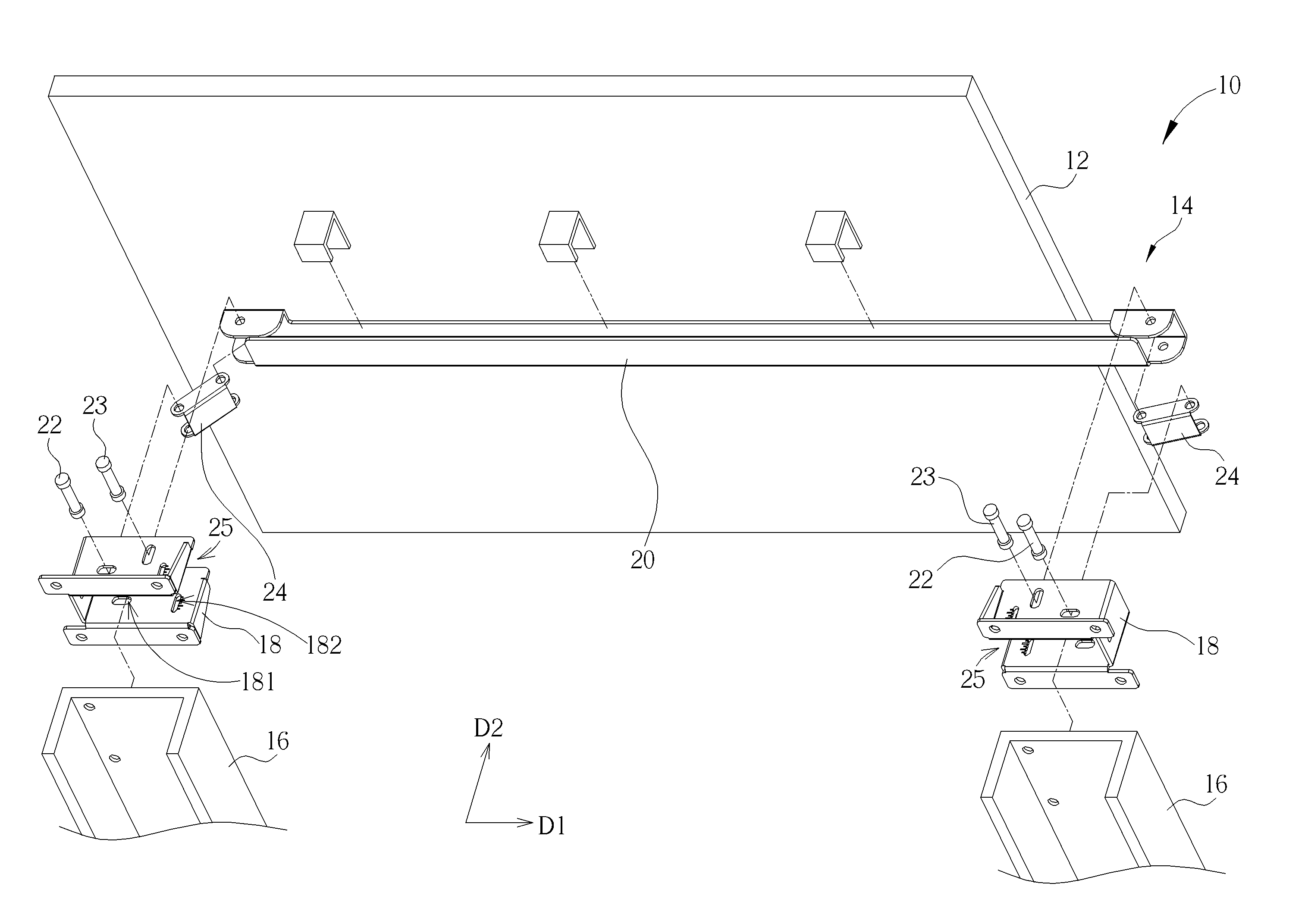
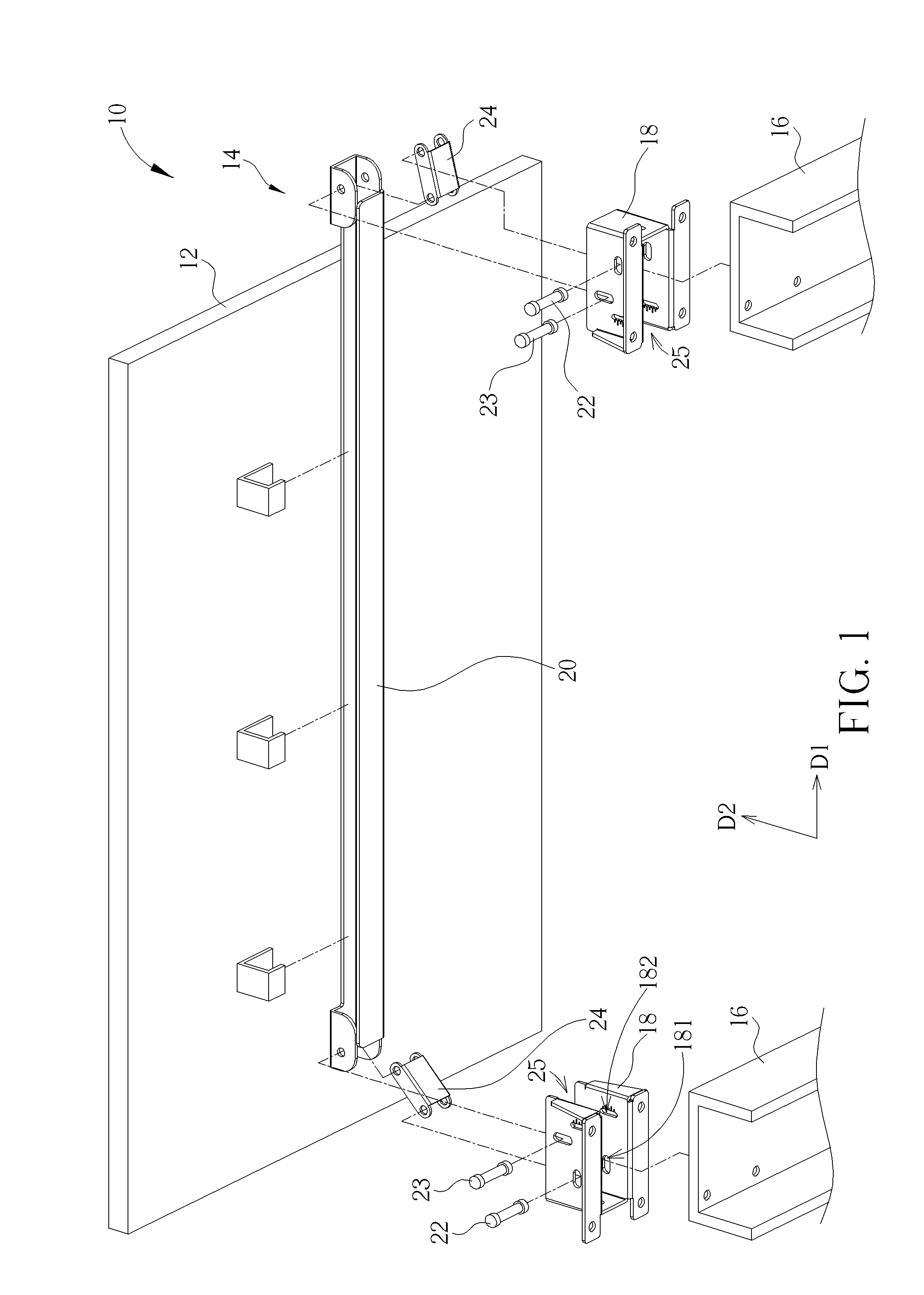
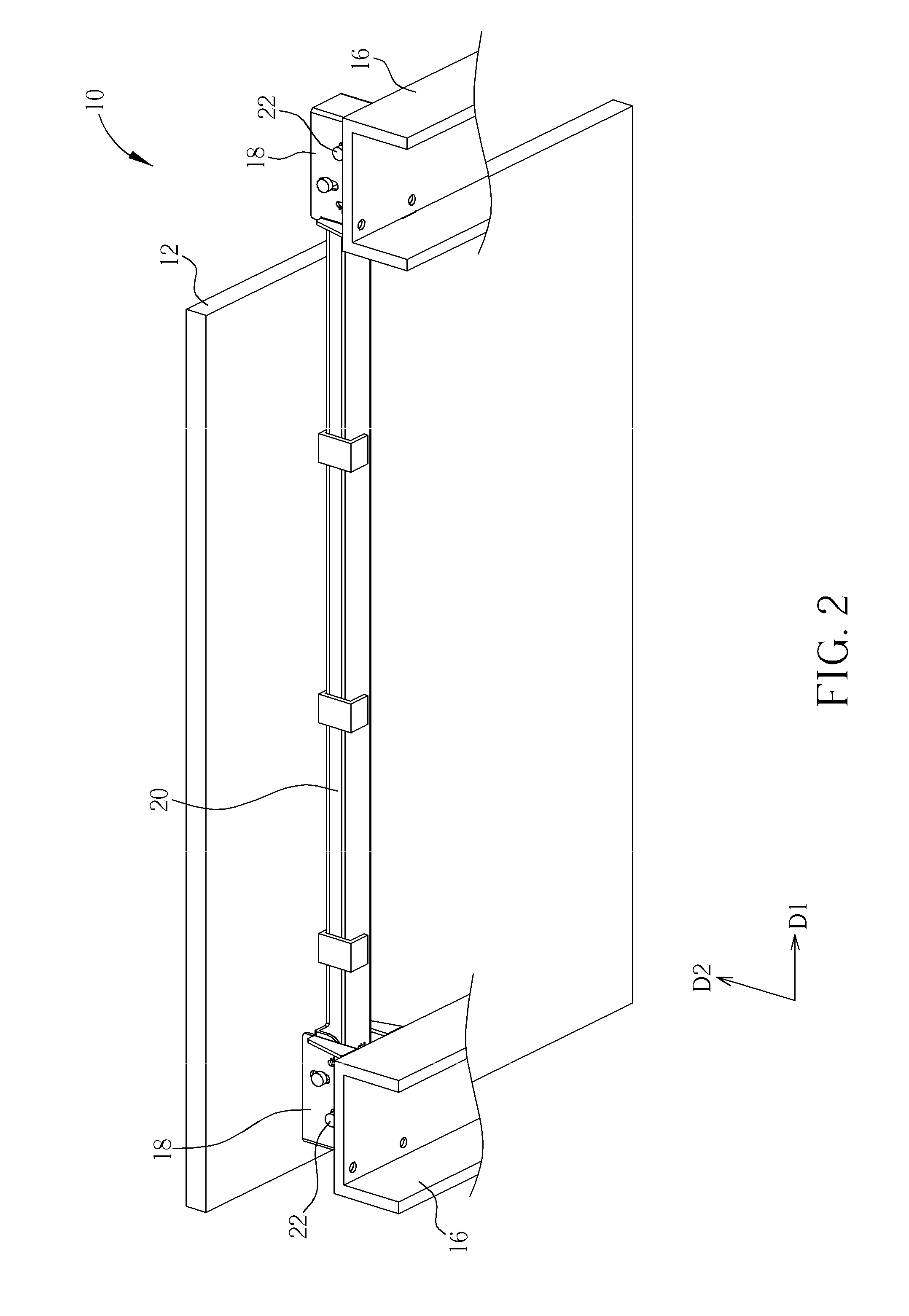
[0017]The adjusting mechanism of the present invention has advantages of simple structure, lower manufacturing cost and easy assembly. The actuating component of the present invention can transfer the application of force into different directions, so the adjusting mechanism can be disposed on the side of the display. The position and the angle of the display relative to the supporter can be adjusted easily and rapidly by controlling the adjusting mechanism at the side of the display, without disassembly of the display from the supporter. Thus, the television wall can be integrated with the plurality of displays via the adjusting mechanisms for preferable sense of sight.

Problems solved by technology

While setting the video-wall structure, all displays are located accurately and are arranged closely by professional measurements and orientation so that it is inconvenient for users, such as businessmen, to install by themselves.
In addition, because hanging means for hanging each display are separate components, the hanging means of the different displays can not be integrated easily so that the whole video-wall structure is complicated.
Thus, design of a simple mounting bracket mechanism for the video-wall structure is an important issue nowadays.

Method used


Image

  • Adjusting mechanism for a display and related mounting system
  • Adjusting mechanism for a display and related mounting system
  • Adjusting mechanism for a display and related mounting system

Examples


first embodiment

[0027]Generally, the mounting system 10 of the present invention can include the plurality of displays 12 arranged in an array, and the adjusting mechanism 14 is disposed on each display 12. One display 12 and the related adjusting mechanism 14 are introduced in the embodiment of the present invention for simplicity. Please refer to FIG. 3 and FIG. 4. FIG. 3 and FIG. 4 are diagrams of the adjusting mechanism 14 in different operating modes according to the present invention. The adjusting mechanism 14 includes two supporters 16, two bridging components 18 respectively disposed on the corresponding supporter 16, a holder 20 installed between the supporters 16 for slidably holding the display 12, two driving components 22 movably disposed on the corresponding bridging component 18, and two actuating components 24. Two ends of the actuating component 24 are respectively connected to the corresponding driving component 22 and the holder 20. The driving components 22 can be pins for conn...

second embodiment

[0033]The connecting component 32 can be slidably installed inside the first slot 181 on the bridging component 18, and the screw component (the driving component 22) passes through the bridging component 18 to be fixed on the connecting component 32. As shown in FIG. 6, the driving component 22 moves relative to the bridging component 18 along the first direction D1, and drives the connecting component 32 to press the actuating component 24 when the driving component 22 is set into the bridging component 18, so that two ends of the actuating component 24 respectively slide along the first slot 181 and the second slot 182 on the bridging component 18 (not shown in FIG. 6), and the holder 20 can be moved for far away the supporter 16 along the second direction D2. On the other hand, the driving component 22 can be moved relative to the bridging component 18 along the direction opposite to the first direction D1 for moving the holder 20 close to the supporter 16, so as to adjust the p...


PUM


Abstract

An adjusting mechanism for a display is disclosed in the present invention. The adjusting mechanism includes a supporter, a bridging component installed on the supporter, a holder for holding the display, a driving component movably disposed on the bridging component, and an actuating component disposed between the driving component and the holder. The driving component moves relative to the bridging component along a first direction to rotate the actuating component, and the actuating component moves the holder relative to the bridging component along a second direction different from the first direction when rotating, so as to adjust a distance between the supporter and the holder.

Description

BACKGROUND OF THE INVENTION[0001]1. Field of the Invention[0002]The present invention relates to an adjusting mechanism for adjusting a position and an angle of a display, and more particularly, to an adjusting mechanism for adjusting a position and an angle of a display so as to be suitable for a video-wall structure and a related mounting system.[0003]2. Description of the Prior Art[0004]In an advanced technology, cathode ray tube (CRT) displays are replaced completely and flat-panel displays (FPD) are main products in a display market. In contrast to huge volume of the conventional cathode ray tube displays, the flat-panel displays have advantages of low power consumption, low radiation, and miniaturized volume. At this time, expansion of dimensions of the flat-panel displays popularizes the miniaturized flat-panel displays in the display market, such as in a domestic display, in an outdoor advertisement, and in an exhibition. A video-wall structure is applied for an enormous fra...

Claims


Application Information

Patent Timeline
Patent Type & Authority Patents(United States)
IPC IPC(8): E04G3/00F16M11/04F16M13/02F16M11/08
CPCF16M13/02F16M11/048F16M11/08
Inventor CHEN, CHIH-HSIUNG
Owner AOPEN
Learn More