Voice coil motor and driving method thereof

a voice coil motor and driving method technology, applied in the direction of instruments, printers, cameras, etc., can solve the problems of increased inability to adjust the digital picture and the lens, and the gap between, so as to reduce the power consumption of the voice coil motor and achieve the effect of rapid

Active Publication Date: 2016-09-20
LG INNOTEK CO LTD
View PDF66 Cites 11 Cited by
  • Summary
  • Abstract
  • Description
  • Claims
  • Application Information

AI Technical Summary

Benefits of technology

[0030]The voice coil motor and a method for driving the voice coil motor according to the present invention has an advantageous effect in that a bobbin mounted with a lens is distanced from an upper surface of a base mounted with an image sensor, and a mover including the bobbin is driven to a direction distanced from the base or a direction approaching the base by applying a forward current or a backward current to a coil block wound on the bobbin, to reduce power consumption of the voice coil motor and to adjust a focus between the lens and the image sensor within a rapid period of time.
[0031]The voice coil motor and a method for driving the voice coil motor according to the present invention has another advantageous effect in that a contact noise generated by driving of the bobbin can be reduced.

Problems solved by technology

A super small digital camera formed on a conventional mobile terminal is disadvantageous in that a gap between an image sensor adapted to change an outside light to a digital image or a digital picture and a lens cannot be adjusted.
The conventional voice coil motor that drives to one direction relative to the base inevitably and disadvantageously needs a driving force larger than that of the elasticity of the leaf spring and a self weight of the bobbin in order to drive the voice coil motor, resulting in increased power consumption of the voice coil motor.
Another disadvantage is that size of a coil wound on the bobbin or a magnet is increased by a driving force larger than the self weight of bobbin and elasticity of the leaf spring to drive the voice coil motor, resulting in an increased overall size of the voice coil motor.
Still another disadvantage is that a focus between the lens and the image sensor is not precisely adjusted to degrade quality of an image, if the leaf spring is deformed.

Method used


Image

  • Voice coil motor and driving method thereof
  • Voice coil motor and driving method thereof
  • Voice coil motor and driving method thereof

Examples


Embodiment Construction

[0042]The advantages, features and methods for achieving the foregoing will be apparent from the accompanying drawings and exemplary embodiments that follow.

[0043]Embodiments of the present invention are described below by way of example only.

[0044]These examples represent the best ways of putting the invention into practice that are currently known to the Applicant although they are not the only ways in which this could be achieved.

[0045]This invention may be embodied in various forms and should not be construed as limited to the embodiments set forth herein. Rather, these embodiments are provided so that this disclosure will be thorough and complete, and will fully convey the scope of the invention to those skilled in the art.

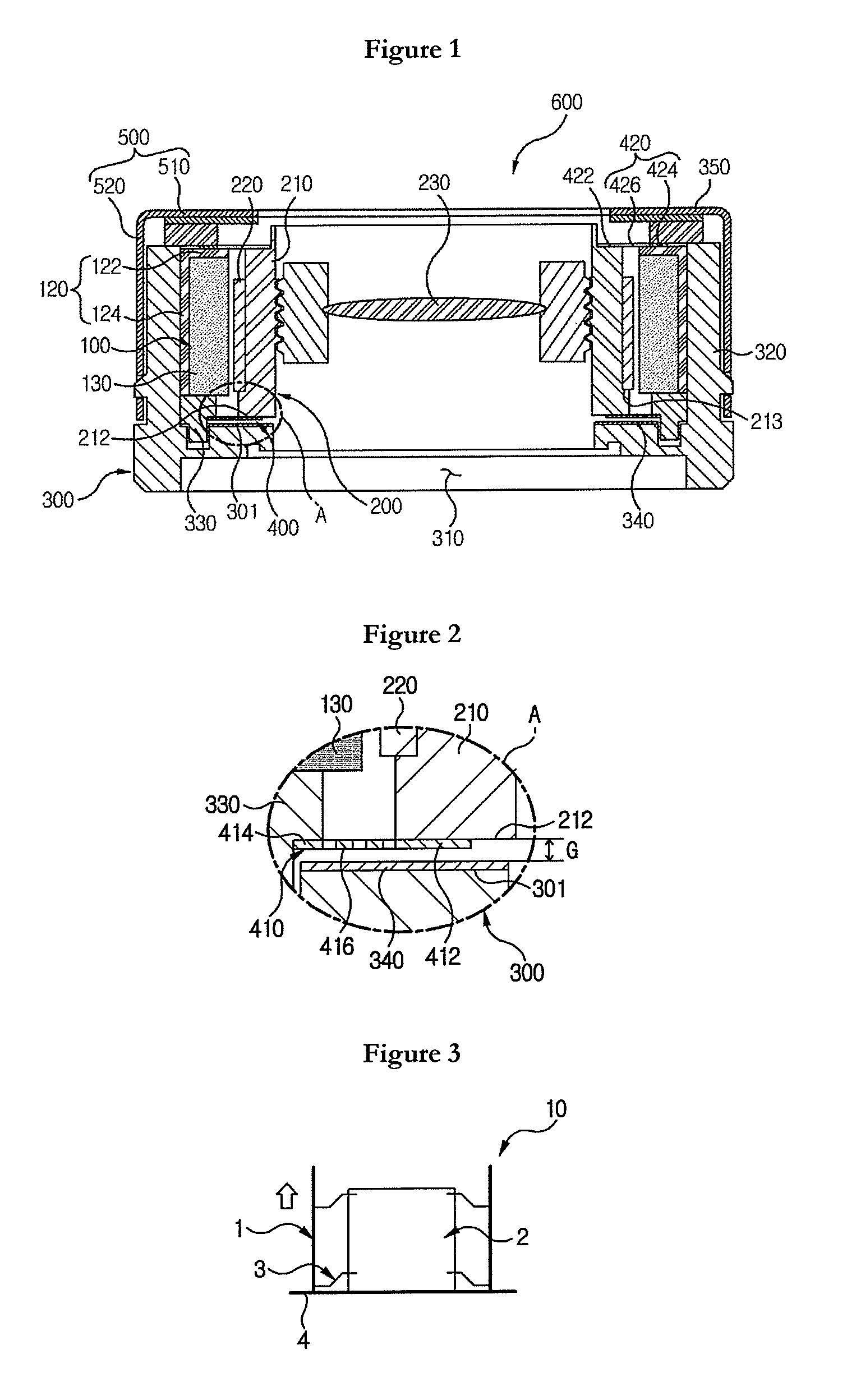
[0046]FIG. 1 is a cross-sectional view illustrating a voice coil motor according to an exemplary embodiment of the present invention, and FIG. 2 is a partial enlarged view of ‘A’ of FIG. 1.

[0047]Referring to FIGS. 1 and 2, a voice coil motor (600) may include...


PUM


Abstract

A voice coil motor (VCM) is disclosed, the VCM including: a stator including a magnet generating a first electromagnetic field; a mover including a bobbin formed with a hollow hole through which light passes and a coil formed on a periphery of the bobbin that generates a second electromagnetic field responsive to the first electromagnetic field; a base fixed at the stator and formed with an opening through which the light passes; and at least one elastic member elastically supporting the bobbin and forming a gap between the bobbin and the base when the coil is not applied with a current.

Description

CROSS-REFERENCE TO RELATED APPLICATIONS[0001]This application is the U.S. national stage application of International Patent Application No. PCT / KR2011 / 001141, filed Feb. 22, 2011, which claims priority to Korean Application No. 10-2010-0108427, filed Nov. 2, 2010, the disclosures of each of which are incorporated herein by reference in their entirety.TECHNICAL FIELD[0002]The present invention relates to a voice coil motor and a driving method of a voice coil motor.BACKGROUND ART[0003]Recently, a mobile terminal embedded with a super small digital camera has been developed. A super small digital camera formed on a conventional mobile terminal is disadvantageous in that a gap between an image sensor adapted to change an outside light to a digital image or a digital picture and a lens cannot be adjusted. However, a lens driving device such as a voice coil motor adapted to adjust a gap between an image sensor and a lens has been recently developed to enable obtainment of an improved di...

Claims


Application Information

Patent Timeline
Patent Type & Authority Patents(United States)
IPC IPC(8): G02B7/09G02B7/08H02K41/035H02K33/18
CPCG02B7/09G02B7/08H02K33/18H02K41/0356H02P25/034H02P25/06G02B7/04H02P7/18H02K33/02H02K41/0354G03B3/10H02P7/06H02P7/025G03B2205/0069
Inventor PARK, SANGOK
Owner LG INNOTEK CO LTD
Why Eureka
Try Eureka