Collapsible pushrod valve actuation system for a reciprocating piston machine cylinder

a technology of reciprocating pistons and pushrods, which is applied in the direction of valve details, valve arrangements, valve drives, etc., to achieve the effect of reducing the lift of the poppet valve and improving the efficiency of part load

Active Publication Date: 2016-09-27
ELECTRO MECHANICAL ASSOCS
View PDF12 Cites 2 Cited by
  • Summary
  • Abstract
  • Description
  • Claims
  • Application Information

AI Technical Summary

Benefits of technology

[0006]A collapsible pushrod system improves the part load efficiency and provides other benefits for reciprocating piston machines by allowing variable valve timing. A collapsible pushrod actuation system configured to reduce a poppet valve lift of a reciprocating piston machine cylinder can comprise: a lifter configured to be actuated by a cam lobe; and a collapsible pushrod device functionally attached to the lifter and configured to either partially or fully collapse. The collapsible pushrod device replaces a standard pushrod.
[0007]In one embodiment, the collapsible pushrod system comprises a driver section, a plunger section, and a deactivation assembly that contains lock pins within a housing. Under normal operating conditions, the pins lock the driver and the plunger sections together to actuate the poppet valve with standard valve lift as provided by the cam lobe. Upon command, for example by oil pressure, the pins are retracted and the plunger telescopes with respect to the driver, thereby reducing or eliminating valve motion.
[0012]In a separate embodiment, a variable oil pressure is used to control the extent to which the collapsible pushrod device with multiple collapser units will collapse.

Problems solved by technology

Consequently, much of the time the engine is operated at a fraction of its design power capability in particular applications involving extensive idling and / or light load operation such as military surveillance vehicles, idling long haul trucks and stationary electric generators, etc.

Method used


Image

  • Collapsible pushrod valve actuation system for a reciprocating piston machine cylinder
  • Collapsible pushrod valve actuation system for a reciprocating piston machine cylinder
  • Collapsible pushrod valve actuation system for a reciprocating piston machine cylinder

Examples


Embodiment Construction

[0027]The following detailed description of the invention is merely exemplary in nature and is not intended to limit the invention or the application and uses of the invention. Furthermore, there is no intention to be bound by any theory presented in the preceding background of the invention or the following detailed description of the invention.

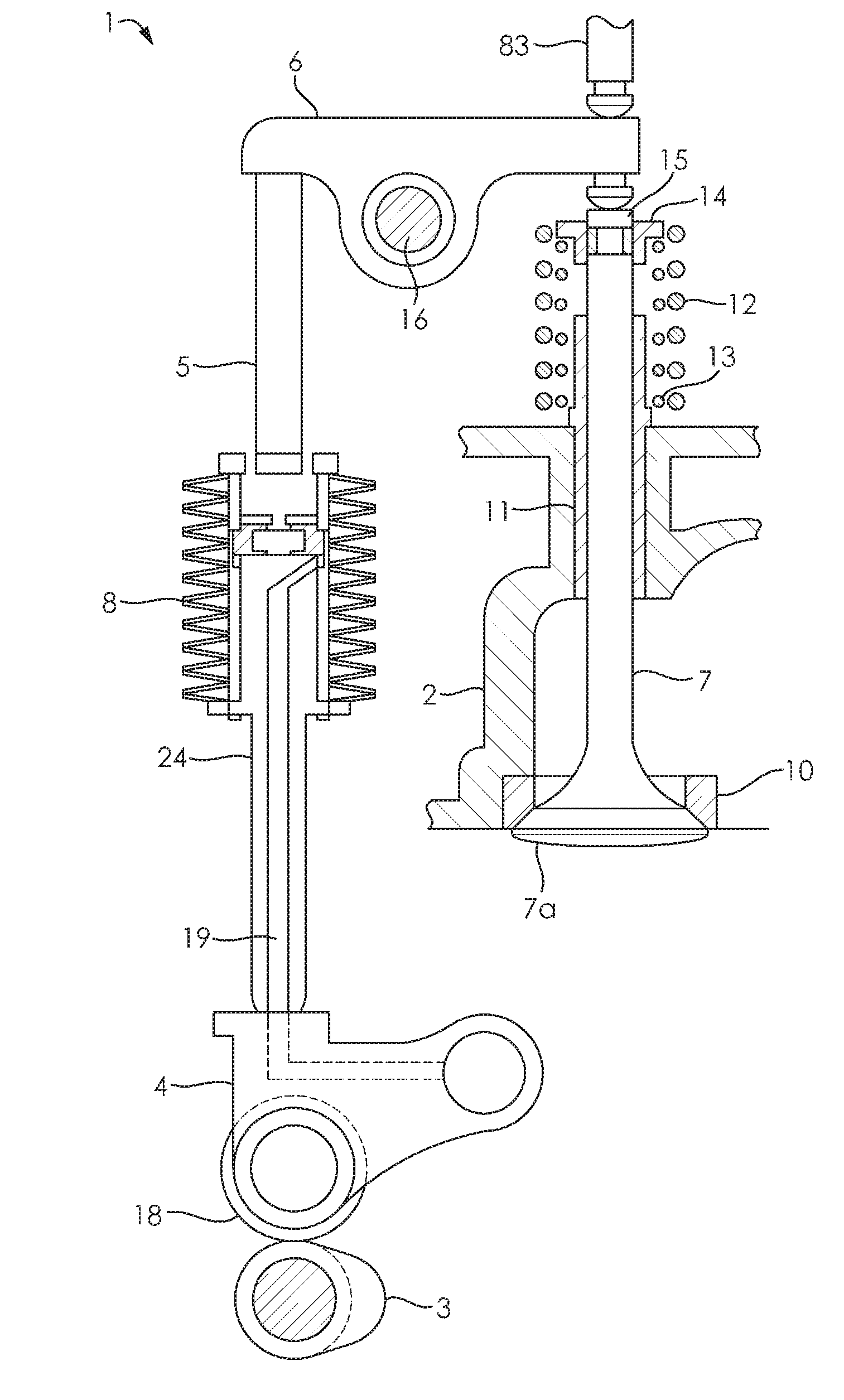
[0028]A collapsible pushrod valve actuation system for a reciprocating piston machine cylinder may be applied to a Diesel engine. Since the design compression ratio of 16:1 up to 23:1 for automotive and heavy duty Diesel engines is for starting conditions, sacrifices are made with regards to warm engine fuel economy, emissions, and optimum power boost. The best economy compression ratio for a warm engine may be as low as 15:1 or even lower. Hence, there exists a need to enable reduced automotive and heavy duty Diesel engine compression ratios, after the engine has been successfully started and warmed-up.

[0029]Since the engine power is larger...


PUM


Abstract

A valve actuation system is described containing a collapsible pushrod device for use in a reciprocating piston machine cylinder such as an engine. The collapsible pushrod device replaces a conventional pushrod. The system can include a driver base, plunger, and a deactivation pin assembly. In normal operation, the pins lock the driver base and plunger together thereby providing regular valve motion. Under selected conditions, the pin assembly controller unlocks the driver base from the plunger. Valve lift is reduced or eliminated. When eliminated, the cylinder is deactivated. The system can vary the effective compression ratio between higher for cold starting and other selected operating conditions and lower for warmed-up running, as well as trap additional exhaust residuals to assist starting and light load. This is especially useful for Diesel engines. Various means may be used to unlock the pins including oil pressure, bi-metal spring temperature, or electromagnetic activation. The telescoping motion which limits the motion of the valve may occur in one or more steps.

Description

CROSS-REFERENCE TO RELATED APPLICATIONS[0001]This application claims the priority benefit of U.S. Provisional Application 62 / 072,242 filed Oct. 29, 2014, which is herein incorporated by reference in its entirety.TECHNICAL FIELD[0002]The present disclosure relates to reciprocating piston machine cylinders. More particularly, the present invention focuses on reciprocating piston machine cylinder valve activation.BACKGROUND[0003]The statements in this section merely provide background information related to the present disclosure. Accordingly, such statements are not intended to constitute an admission of prior art.[0004]Poppet valves are widely used in Diesel engines, spark-ignited engines, and other reciprocating piston machines. Diesel engines are widely used in heavy duty vehicles, light duty vehicles, electrical generators, and a variety of other applications. Engine design compression ratio is a compromise between power, economy, emissions, and cold startability. In Diesel engine...

Claims


Application Information

Patent Timeline
Patent Type & Authority Patents(United States)
IPC IPC(8): F01L1/34F01L1/04
CPCF01L1/34F01L1/04F01L1/18F01L1/181F01L1/46F01L1/462F01L13/0005F01L13/0031F01L2001/054F01L1/146F01L2305/00
Inventor PATTERSON, DONALD JAMESMORRISON, KEVIN MICHAELSCHWARTZ, GEORGE BYRON
Owner ELECTRO MECHANICAL ASSOCS
Why Eureka
Try Eureka