Exhaust duct for a gas turbine engine

a gas turbine engine and exhaust duct technology, which is applied in the direction of machines/engines, turbine/propulsion fuel heating, lighting and heating apparatus, etc., can solve the problems of reducing the efficiency and power output of the gas turbine engine itself, reducing the efficiency of the gas turbine engine itself, and enthalpy loss negatively affecting efficiency, so as to improve the turbine output of the gas turbine engine, reduce the flow through the compressor, and reduce the effect of compressor power consumption

Pending Publication Date: 2021-12-23
GENERAL ELECTRIC TECH GMBH
View PDF5 Cites 0 Cited by
  • Summary
  • Abstract
  • Description
  • Claims
  • Application Information

AI Technical Summary

Benefits of technology

[0019]In further embodiments, the power station may essentially be a power station of the type disclosed in US 2019 / 0195131. The power station comprises, besides the gas turbine engine, a turbocharging appliance, wherein the turbocharging appliance comprises at least one low pressure compressor, at least one high pressure compressor, and at least one turbine for driving said compressors. Each compressor may be arranged on a common shaft with and driven by an individual turbine. The turbocharging appliance then may comprise at least one low pressure turbocharger and one or more high pressure turbochargers, wherein a compressor of a low pressure turbocharger delivers fluid into a high pressure compressor. It may be the case that multiple low pressure turbochargers are arranged in parallel to each other and in series with one single high pressure turbocharger, so as to, for instance, use identical turbochargers while accounting for the different volume flows in the high pressure and low pressure compressors. In other embodiments, it may be provided that one or more high pressure compressors and one or more low pressure compressors are fluidly arranged such that a compressor of a low pressure turbocharger delivers fluid into a high pressure compressor, while being provided on a common shaft with a, and in particular with one single, turbine for driving the compressors. A compressor outlet of the at least one low pressure compressor is fluidly connected to the inlet ports of the silencer baffles configured as heat exchange devices and to a compressor inlet of the at least one high pressure compressor. An intercooler may be fluidly interposed between the compressor outlet of the at least one low pressure compressor and the compressor inlet of the at least one high pressure compressor. The outlet ports of the silencer baffles configured as heat exchange devices are fluidly connected to a turbine inlet of the at least one turbine of the turbocharging appliance. A turbine outlet of the at least one turbine of the turbocharging appliance is fluidly connected to a back pressure control device, and a compressor outlet of the at least one high pressure compressor is connected to the working fluid flow path of the gas turbine engine downstream the compressor of the gas turbine engine and upstream the combustor of the gas turbine engine, i.e., fluidly connected to a combustor of the gas turbine engine. Thus, the waste heat recovered in the heat exchange baffles may be used to drive external compressors for supplying additional air to the combustor of the gas turbine engine and thus enhance the turbine output of the gas turbine engine and / or reduce the flow through the compressor of the gas turbine engine, thus reducing the power consumption of the compressor of the gas turbine engine. The back pressure valve is utilized to control the discharge pressure of the high pressure compressor of the turbocharging device.

Problems solved by technology

Hence, with the exhaust gases large enthalpy flows, which had, prior to expansion in the expansion turbine, been added in combusting fuel, are discharged into the atmosphere and get lost for technical use.
The resulting loss of enthalpy negatively impacts efficiency.
However, building a combined cycle power plant, wherein a steam turbine as a bottoming cycle uses the exhaust energy from the gas turbine engine, requires a significant capital investment which makes this technology, despite the superior overall efficiency, only economically attractive if the plant can be operated at least essentially as a base load power plant, for instance more than 5000 hours a year and at a high power output of, for instance, at least 75% of the rated power output.
Moreover, the numerous installations inside the exhaust duct yield an additional pressure loss, hence in turn reducing the efficiency and power output of the gas turbine engine itself.
In addition, a heat recovery steam generator requires space that might not always be available.
In particular, installing a heat recovery steam generator may not be an option to add to an existing single cycle gas turbine engine power station.

Method used


Image

  • Exhaust duct for a gas turbine engine
  • Exhaust duct for a gas turbine engine
  • Exhaust duct for a gas turbine engine

Examples


Embodiment Construction

[0039]The herein described subject matter will be more appreciated by a person having ordinary skill in the art by virtue of exemplary embodiments shown in the accompanying drawings and outlined below. It shall be understood that these exemplary embodiments are merely shown for illustrative purposes to enable a better appreciation of the herein described subject matter and shall be understood as not limiting the subject matter outlined in the claims.

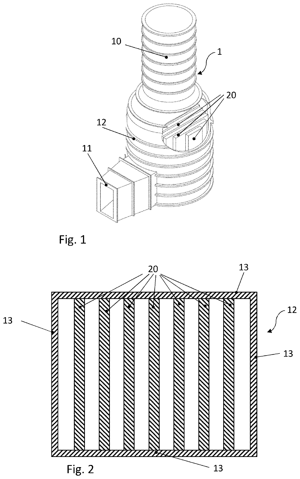
[0040]FIG. 1 shows an example of an exhaust duct 1 of a gas turbine engine. The exhaust duct 1 comprises a stack 10. An exhaust duct transition section 11 is configured to connect with the downstream end of the gas turbine engine 50 (shown schematically in FIGS. 8-12). A silencer section 12 of the exhaust duct comprises silencer baffles 20, which are visible in the present part-sectional view. In the depicted example, the stack 10 and the silencer section 12 have rounded cross-sections, while the exhaust duct transition section 11 is sho...


PUM


Abstract

Disclosed is an exhaust duct (1) for a gas turbine engine (50), comprising a silencer section (12). At least two plate-shaped silencer baffles (20) are provided inside the silencer section (12). At least one of the plate-shaped silencer baffles is configured as a heat exchange device in that it comprises at least one internal cavity (22) suitable for receiving a heat exchange fluid and leakproof with respect to the interior of the exhaust duct, wherein the at least one internal cavity is fluidly connected to the outside of the exhaust duct at an inlet port and an outlet port (23, 24). This device is useful for recuperating exhaust heat from exhaust gases of the gas turbine engine without the expense and additional space required for providing a heat recovery steam generator.

Description

CROSS-REFERENCE TO RELATED APPLICATIONS[0001]This application claims priority pursuant to 35 U.S.C. 119(a) to European Patent Application No. 20181760.8, filed Jun. 23, 2020, which application is incorporated herein by reference in its entirety.TECHNICAL FIELD[0002]The present disclosure relates to an exhaust duct for a gas turbine engine of the type set forth in the claims.BACKGROUND OF THE DISCLOSURE[0003]The exhaust gases of gas turbine engines, after exiting the expansion turbine, still are at several hundred degrees Celsius, and typically may be in a range from 500° C.-600° C. under high part load and full load conditions in contemporary gas turbine engines. Hence, with the exhaust gases large enthalpy flows, which had, prior to expansion in the expansion turbine, been added in combusting fuel, are discharged into the atmosphere and get lost for technical use. The resulting loss of enthalpy negatively impacts efficiency.[0004]It is known from the art to recover exhaust enthalpy...

Claims


Application Information

Patent Timeline
Patent Type & Authority Applications(United States)
IPC IPC(8): F01D25/30F02C6/08F02C6/16F02C7/224F02C7/08
CPCF01D25/305F02C6/08F02C6/16F02C7/224F05D2250/185F05D2240/126F05D2260/213F05D2260/232F05D2260/96F02C7/08F01D25/30F02C6/00F02C6/18F02C7/24F02C3/04F05D2220/60F22B1/1815F05D2250/312Y02E20/16Y02E60/16Y02P80/15F02C7/045F01N5/02F02C7/10
Inventor FAQIHI, BOURIA MOHAMEDPRABHUDHARWADKAR, DEORASZIA, JALALGHAITH, FADI
Owner GENERAL ELECTRIC TECH GMBH
Why Eureka
Try Eureka