Unit inverter system

a technology of inverter system and inverter, which is applied in the direction of dc-ac conversion without reversal, process and machine control, instruments, etc., can solve the problems of reducing the conversion power of the inverter, and the adverse effect of the resonant current on the system, so as to improve the partial load efficiency

Inactive Publication Date: 2011-04-21
FUJI ELECTRIC CO LTD
View PDF5 Cites 6 Cited by
  • Summary
  • Abstract
  • Description
  • Claims
  • Application Information

AI Technical Summary

Benefits of technology

[0019]According to the invention, when reducing the quantity of inverters in a unit inverter where the power to be converted fluctuates, the gate signal of the semiconductor element of the inverter circuit is turned off after the output current of the inverter to be stopped is reduced to a predetermined value or lower. As a result of this, it is possible to cause a minimum necessary quantity of units to operate while suppressing the adverse effect on the system of a sharp power fluctuation, a resonant current, and the like, and it is possible to improve the partial load efficiency.

Problems solved by technology

When using the unit inverter in a dispersed power source connected to a power generation source whose power constantly fluctuates, such as in solar light or wind power generation, it often happens that the converted power thereof is smaller than the device capacity.
Herein, in the case of stopping the gate signal of one portion of the operating units, there is a problem in that the balance reactor and filter capacitor connected to the relevant unit form a resonant circuit, and the resonant current thereof has an adverse effect on the system.

Method used


Image

  • Unit inverter system
  • Unit inverter system
  • Unit inverter system

Examples


first embodiment

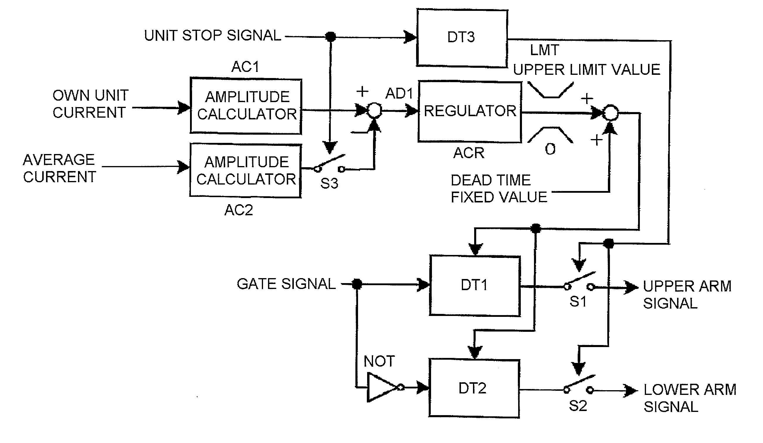
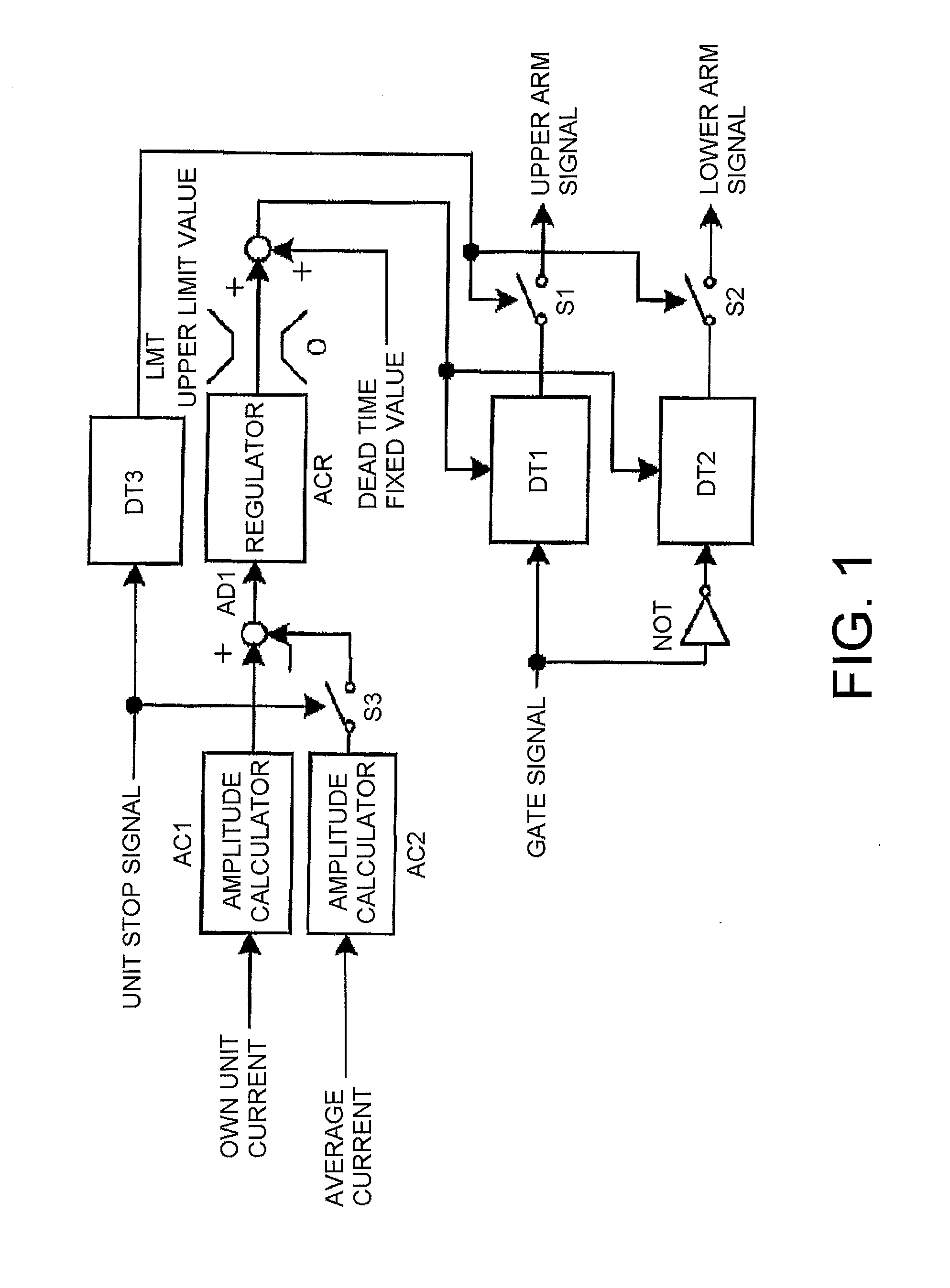
[0030]A first embodiment of the invention is shown in FIG. 1. The embodiment is an example in a case of using a current amplitude value as an average value of each unit inverter output current, and as an own unit current value, at a time of steady operation. A dead time regulator has a configuration which adjusts dead time in such a way that an own unit current amplitude value of each unit calculated by an amplitude calculator AC1, and an in-unit average current amplitude value calculated by an amplitude calculator AC2, match.

[0031]The own unit current output by each unit, and the average current amplitude value, are calculated by the amplitude calculators AC1 and AC2. A deviation of the two current values is obtained by an adder AD1, and input into an regulator ACR. The output of the regulator ACR is input into an upper and lower limit limiter LMT which has 0 as a lower limit value and a fixed value as an upper limit value. The output of the limiter LMT is then added by an adder AD...

second embodiment

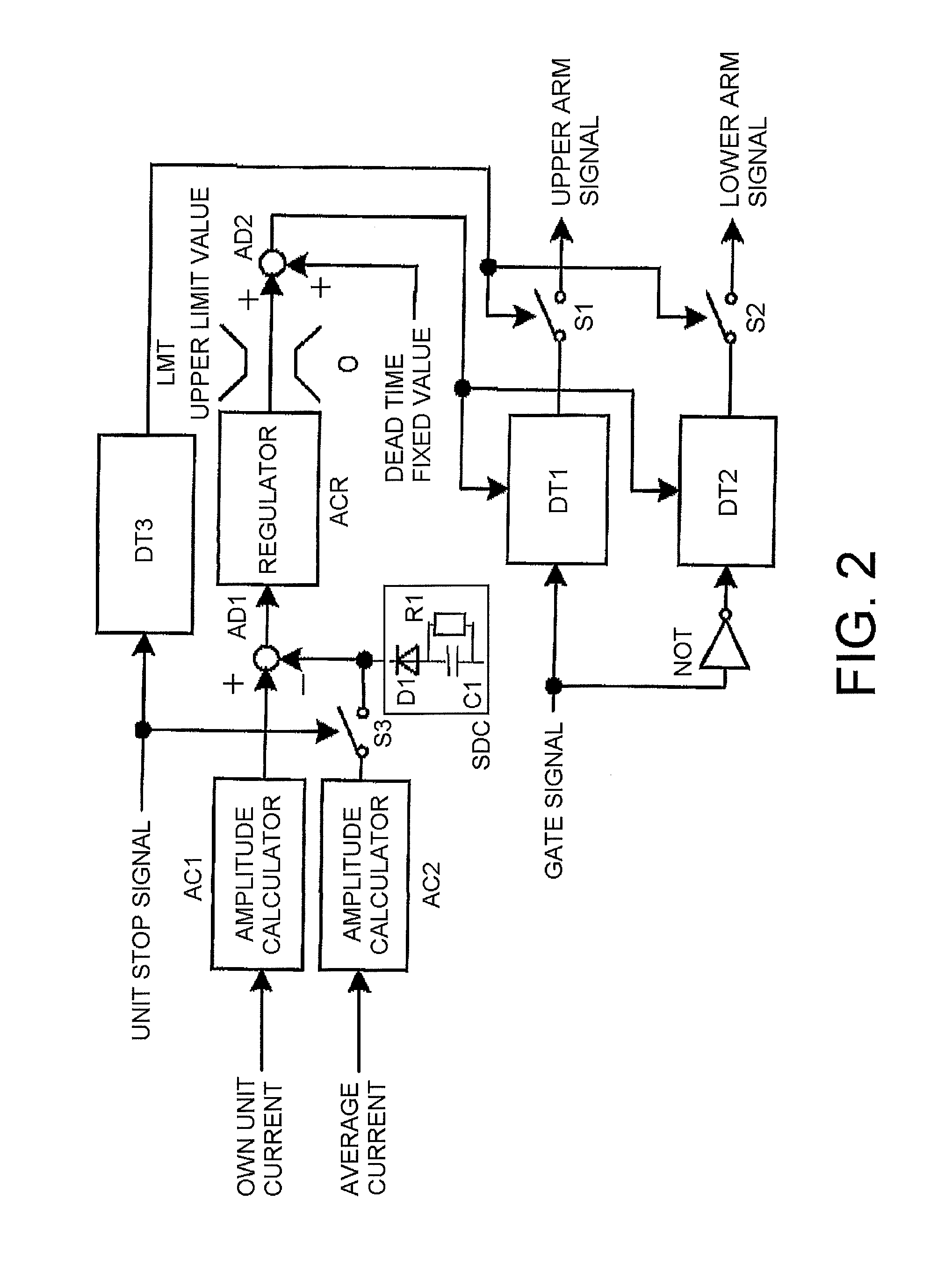
[0034]A second embodiment of the invention is shown in FIG. 2. A difference from the first embodiment lies in the point that a voltage soft reduction circuit SDC configured of a resistor R1, a diode D1, a capacitor C1, and the like, is connected to the output of the switch S3 that is connected to the output of the average current amplitude calculator AC2.

[0035]On the switch S3 being turned off by the input of the unit stop signal, the output of the current regulator ACR gradually rises toward the upper limit value of the limiter LMT in accordance with a voltage reduction of the voltage soft reduction circuit SDC. As a result of this, the dead time increases more slowly than in the first embodiment, it is possible to reduce the inverter output current gently, thereby reducing a rate of change of power to the system. This means that it is possible to more effectively suppress the adverse effect on the system of power fluctuation, a resonant current, and the like. It being sufficient t...

third embodiment

[0036]A third embodiment of the invention is shown in FIG. 3. A dead time regulator adjusts the dead time in such a way that the own unit current amplitude value of each unit calculated by the amplitude calculator AC1, and the in-unit average current amplitude value calculated by the calculator AC2, match.

[0037]The amplitude value of the own unit current output by each unit, and the average current amplitude value, are calculated by the amplitude calculators AC1 and AC2. A deviation of the two values is obtained by the adder AD1, and input into the regulator ACR. The output of the regulator ACR is input into the upper and lower limit limiter LMT which has 0 as the lower limit value, and a fixed value as the upper limit value. The output of the limiter LMT is then added by the adder AD2 to the dead time fixed value for preventing a short circuit of the upper and lower arms of the inverter. The added value is used as the delay time of the on-delay circuits DT1 and DT2 into which a gat...


PUM


Abstract

In a unit inverter system where multiple unit inverters are connected in parallel, the quantity of operating unit inverters is determined in accordance with an amount of power to be converted. A gate signal of a semiconductor switching element of a unit inverter is turned off after an output current of the inverter is reduced when reducing the quantity of inverter units, thereby improving the partial load efficiency of the system without an adverse effect on the system. A regulator connected to the inverter determines dead time of the inverter according to the output current value and an average output current value of the unit inverters, waits for the determined dead time so as to reduce the output current of the unit inverter, and then turns off the gate signal.

Description

CROSS-REFERENCE TO RELATED APPLICATION[0001]This application claims priority under 35 U.S.C. §119 from Japanese Patent Application 2009-238294, filed Oct. 15, 2009, the entirety of which is incorporated herein by reference.BACKGROUND OF THE INVENTION[0002]1. Technical Field[0003]The present invention relates to a technology of controlling a unit inverter system where a dispersed power source whose power fluctuates, such as in solar battery or wind power generation, includes multiple unit inverters, and a quantity of operating unit inverters is changed in accordance with power generated. The present invention also relates to a dead time regulator that adjusts dead time of a unit inverter to reduce an output current of the unit inverter before stopping the unit inverter to reduce the quantity of operating unit inverters.[0004]2. Related Art[0005]The configuration of a unit inverter system using heretofore known technology, where multiple inverter units are connected in parallel, and t...

Claims


Application Information

Patent Timeline
Patent Type & Authority Applications(United States)
IPC IPC(8): H02M1/36
CPCH02M7/493H02M1/36
Inventor FUJII, KANSUKE
Owner FUJI ELECTRIC CO LTD
Why Eureka
Try Eureka