Touch panel

a touch panel and touch technology, applied in the field of touch panels, can solve the problems of degrading process efficiency, affecting damage to wire electrodes, etc., and achieve the effects of improving process efficiency, improving process efficiency, and improving the reliability of touch panels

Active Publication Date: 2016-09-27
LG INNOTEK CO LTD
View PDF18 Cites 4 Cited by
  • Summary
  • Abstract
  • Description
  • Claims
  • Application Information

AI Technical Summary

Benefits of technology

[0011]The embodiment provides a touch panel which can be easily provided, and includes a wire electrode having reduced resistance.
[0015]Therefore, the process of separately forming the wire electrode can be omitted, so that the number of processes can be reduced to improve the process efficiency.
[0016]In other words, at least one of the first and second wire electrodes is connected with the sensing electrode. If one of the first and second wire electrodes is cracked so that the cracked wire electrode does not perform a wire function, since the other wire electrode can serve as a wire, the reliability of the touch panel can be improved.
[0017]In addition, the first and second wire electrodes are formed in a parallel structure, that is, at a predetermined thickness on the inactive area, so that only resistance approximate to that of a conventional wire electrode including a metallic material is generated even if the wire electrode includes a transparent conductive material such as ITO. Accordingly, the efficiency of the touch panel can be improved.

Problems solved by technology

In the resistive type touch panel, the repeated use thereof may degrade the performance thereof, and cause scratches.
In other words, the wire electrode is provided on the step difference part of the printing layer, so that the wire electrode may be damaged as the wire electrode may be cracked or disconnected in the step difference part.
In addition, as the sensing electrode and the wire electrode are provided through mutually different processes, the process efficiency may be degraded.

Method used


Image

  • Touch panel
  • Touch panel
  • Touch panel

Examples


first embodiment

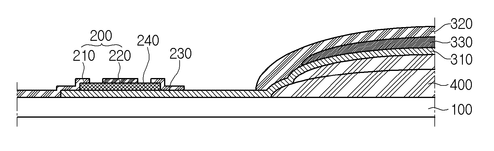
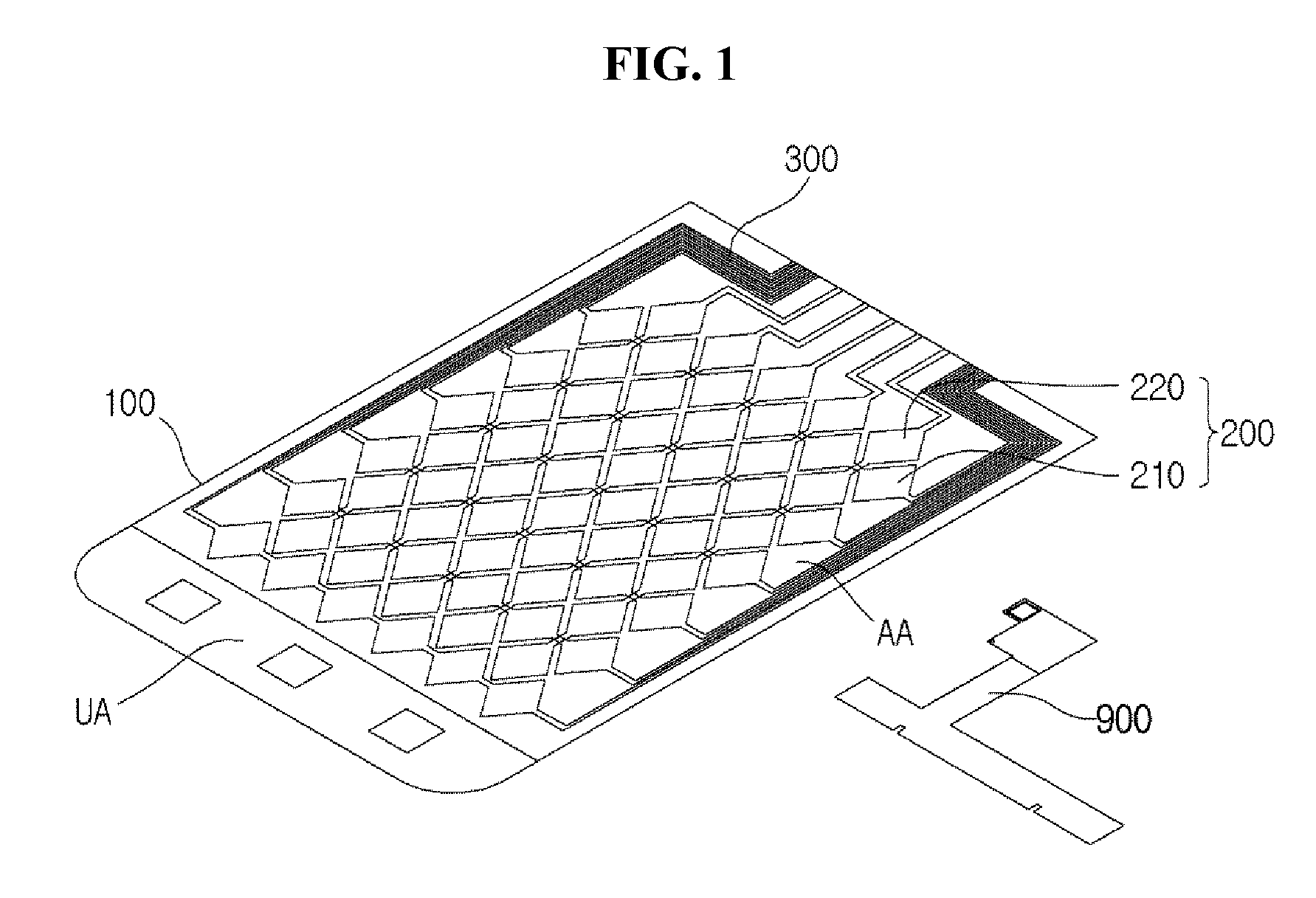
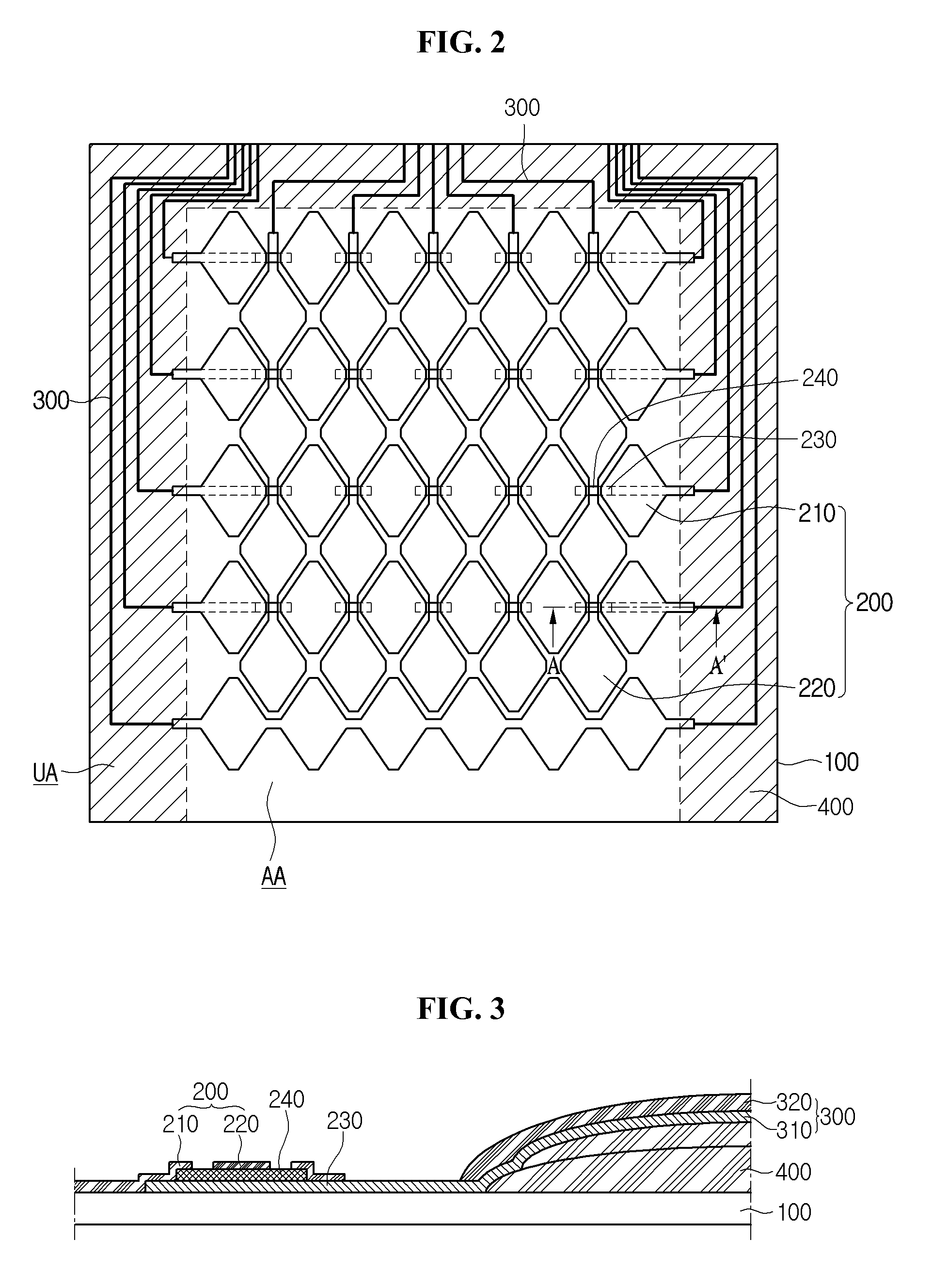
[0036]Referring to FIGS. 2 to 5, in the touch panel the bridge electrode 230 may be provided on the active area AA of the cover substrate 100, and the first insulating layer 240 may be provided on the bridge electrode 230. In detail, the first insulating layer 240 may partially cover the bridge electrode 230. Accordingly, the bridge electrode 230 may include a close area covered by the first insulating layer 240 and an open area that is not covered by the first insulating layer 240.

[0037]The first sensing electrode 210 may make contact with the bridge electrode 230. In other words, the first sensing electrode 210 may make contact with the open area of the bridge electrode 230.

[0038]In addition, the second sensing electrode 220 may be provided on the first insulating layer 240. In other words, the second sensing electrode 220 may be provided on the close area of the bridge electrode 230.

second embodiment

[0039]Referring to FIGS. 6 to 9, in a touch panel the first and second sensing electrodes 210 and 220 may be provided on the active area AA of the cover substrate 100, and the first insulating layer 240 may be provided to surround the first and second sensing electrodes 210 and 220.

[0040]The bridge electrode 230 may be provided on the first insulating layer 240. In addition, the first insulating layer 240 may be provided therein with a through hole. The bridge electrode 230 may be connected with the sensing electrode 220 through the through hole.

[0041]In the same manner, a plurality of first sensing electrodes are connected with a plurality of second sensing electrodes on the cover substrate 100. In other words, the first sensing electrodes are not electrically connected with the second sensing electrodes by the insulating layer on the active area of the cover substrate 100.

[0042]Although the above description has been made in that the sensing electrode is provided on the cover sub...


PUM


Abstract

Disclosed is a touch panel. The touch panel includes a cover substrate comprising an active area and an inactive area, a sensing electrode on the active area, and a wire electrode on the inactive area. The wire electrode includes a material the same as a material constituting the sensing electrode.

Description

CROSS-REFERENCES TO RELATED APPLICATION[0001]This application claims the benefit under 35 U.S.C. §119 of Korean Patent Application No. 10-2013-0113525, filed Sep. 24, 2013, which is hereby incorporated by reference in its entirety.BACKGROUNDTechnical Field[0002]The embodiment relates to a touch panel.[0003]Recently, a touch panel, which performs an input function through the touch of an image displayed on a display by an input device such as a stylus pen or a hand, has been applied to various electronic appliances.[0004]The touch panel may be mainly classified into a resistive touch panel and a capacitive touch panel. In the resistive touch panel, glass is shorted with an electrode due to the pressure of the input device so that a touch point is detected. In the capacitive touch panel, the variation in capacitance between electrodes is detected when a finger of the user is touched on the capacitive touch panel, so that the touch point is detected.[0005]In the resistive type touch pa...

Claims


Application Information

Patent Timeline
Patent Type & Authority Patents(United States)
IPC IPC(8): G06F3/044
CPCG06F3/044G06F2203/04103G06F3/0443G06F3/0446G06F3/0416
Inventor KIM, JONG IL
Owner LG INNOTEK CO LTD
Why Eureka
Try Eureka