Sytems and method for CO2 capture and H2 separation with three water-gas shift reactions and warm desulfurization

a technology of cosub>2 and hsub>2, which is applied in the direction of combustible gas catalytic treatment, combustible gas purification/modification, sustainable manufacturing/processing, etc., can solve the problems of complex pollution control problems, reduce the thermal value of syngas, and reduce the efficiency of combined cycle plants

Active Publication Date: 2016-10-04
GE INFRASTRUCTURE TECH INT LLC
View PDF25 Cites 1 Cited by
  • Summary
  • Abstract
  • Description
  • Claims
  • Application Information

AI Technical Summary

Benefits of technology

[0012]The application FIGURE is a process flow diagram depicting the exemplary process steps and major pieces of equipment necessary to carry out the present invention, namely to remove the unwanted sulfur components, efficiently convert CO to CO2, separate out the hydrogen fuel fraction and create an improved supplemental fuel source containing additional hydrogen for use in a combined cycle plant.

Problems solved by technology

However, in all such systems, the end product has less than half the energy density of natural gas and contains hydrogen, large amounts of carbon monoxide and at least some carbon dioxide.
As noted, a major concern of most gasification systems which produce syngas, particularly those relying on coal as a primary fuel, relates to the high volume percent of carbon monoxide and carbon dioxide, as well as the presence of sulfur compounds (such as H2S and COS) and even nitrogen compounds—all of which reduce the thermal value of the syngas, create complex pollution control problems and decrease combined cycle plant efficiencies.
Thus, in recent years, a number of efforts have been made, with only limited success, to reduce the amount of sulfur and other non-fuel components in the syngas feed without jeopardizing the thermodynamic efficiency of a plant or increasing the capital expenditures necessary to satisfy strict federal and state emission control standards.
Despite those successes, Selexol is considered an expensive and complex alternative for eliminating sulfur and CO2 from a syngas feedstock since it involves cooling high temperature gases from the gasifier to low process temperatures.
Although some advances have been made in converting and purifying syngas produced from coal gasification, e.g., as part of an integrated gasification combined cycle (“IGCC”) plant, the commercialization of most “coal-to-hydrogen” technologies has been hindered by the high capital costs associated with removing inorganic impurities, particularly the sulfur present in domestic coal which ultimately form oxides and / or H2S that create serious environmental concerns.
In addition, most known liquid absorption units for H2S involve low temperature processes that require that the entire gas stream be cooled, resulting in additional energy losses and lower efficiencies.
However, a typical decarbonization plant is complex because it requires the use of one or more catalytic reactors and reformers as essential components.
Decarbonization systems can also be thermodynamically inefficient and costly to install and operate.
For example, a decarbonization process can result in an 8-12% penalty in the overall plant efficiency due to the energy required and released during the reforming process.
As for the hydrogen present in syngas, some conventional systems are capable of separating fuel grade H2 from a syngas feedstock but require a large number of unit operations such as multiple absorption and desorption columns and a large footprint within an existing plant.
However, the use of membranes alone does not produce a “clean” syngas product free from residual sulfur, carbon monoxide and carbon dioxide constituents.
In addition, the known hydrogen-selective membranes are not permeable to carbon monoxide and thus unable to transfer the separated gas to a fuel-rich permeate stream.

Method used


Image

  • Sytems and method for CO<sub>2 </sub>capture and H<sub>2 </sub>separation with three water-gas shift reactions and warm desulfurization
  • Sytems and method for CO<sub>2 </sub>capture and H<sub>2 </sub>separation with three water-gas shift reactions and warm desulfurization

Examples


Embodiment Construction

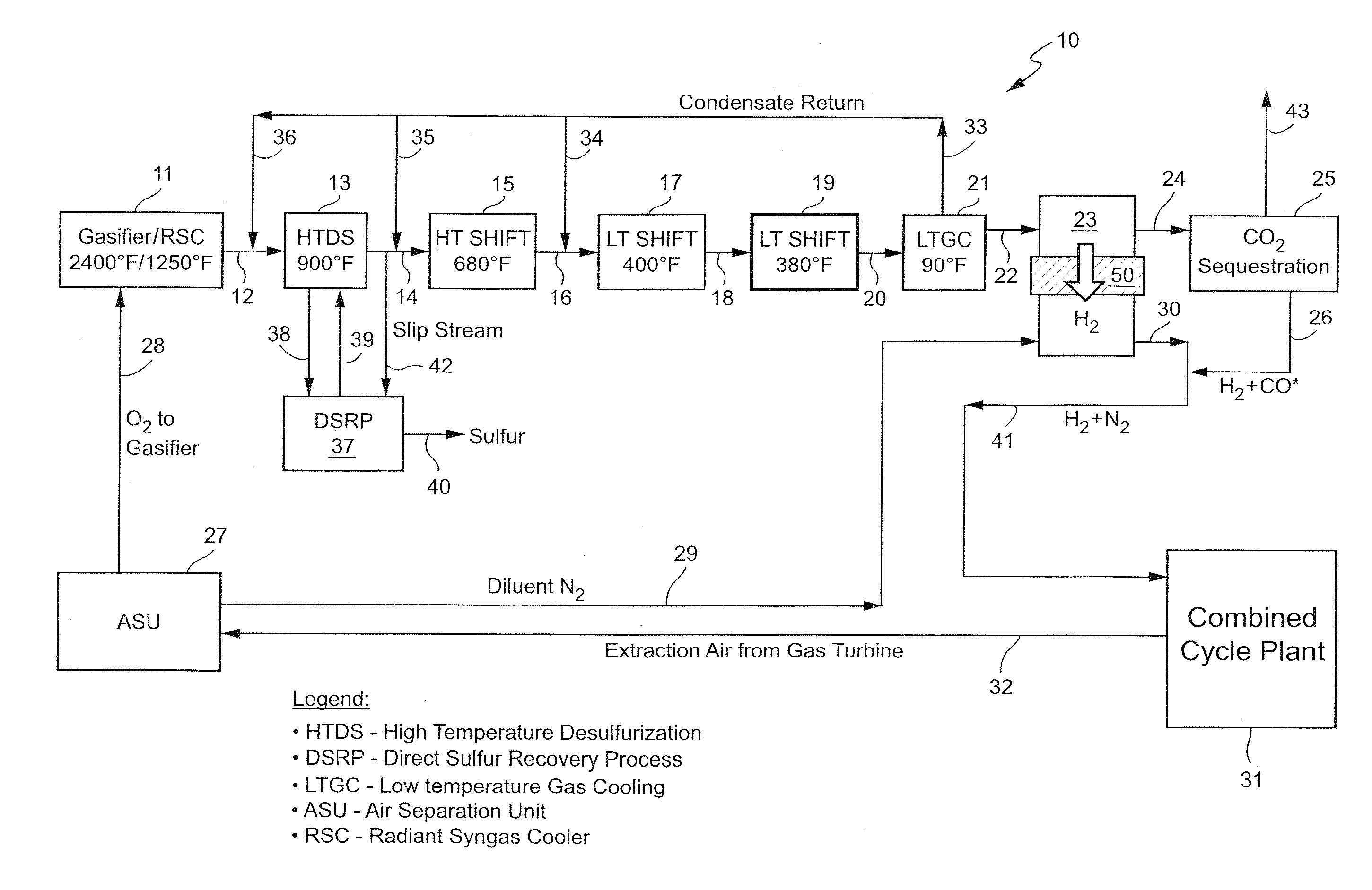
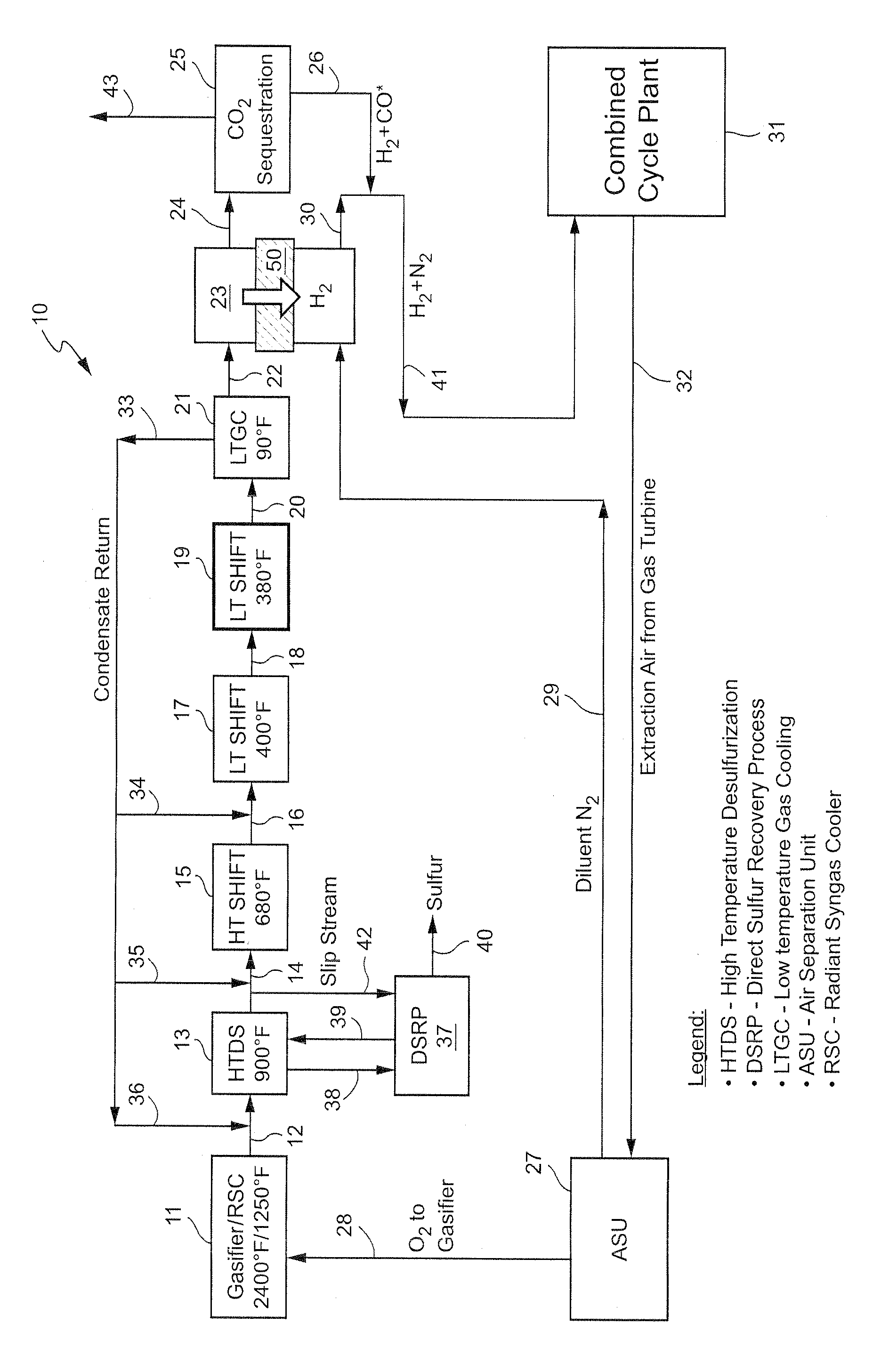
[0013]As noted, the present invention provides a new, and more cost effective, method for removing sulfur compounds and CO from a syngas feed without requiring any use of a conventional solvent-based acid gas removal (“AGR”) subsystem as part of the process. In order to achieve that objective, the invention relies for the first time on the combination of a high temperature desulfurization step and a plurality of water-gas shift reactions and related heat generation steps. The end result is the removal of all residual sulfur and a complete (almost 100% conversion) shift of the CO resident in the syngas to CO2, thereby completely eliminating the need for any solvent-based process such as Selexol. The process also results in the virtual elimination of CO in the syngas feed without any need for a catalytic converter to handle any residual CO left in the exhaust, again unlike Selexol or other known prior art processes. The new system also effectively isolates and separates any hydrogen p...


PUM

PropertyMeasurementUnit
temperatureaaaaaaaaaa

Abstract

A method and system for capturing and isolating carbon dioxide and hydrogen gases from a high temperature synthesis gas stream containing a substantial amount of CO and sulfur compounds for use as a “clean” supplemental fuel, comprising the steps of reducing the temperature of the high temperature synthesis gas stream, removing substantially all of the sulfur compounds present in the synthesis gas, converting a first portion of CO to carbon dioxide in a first high temperature water-gas shift reaction, converting a second portion of CO to carbon dioxide using a second low temperature water-gas shift reaction, converting a third portion of CO to carbon dioxide using a third low temperature water-gas shift reaction and then separating out substantially all hydrogen present in the treated synthesis gas stream.

Description

[0001]The present invention relates to a method and system for removing undesirable chemical constituents from a synthesis gas stream in order to produce a more fuel efficient feed to a gas turbine engine in a combined cycle plant, as well as for other commercial uses relying on clean hydrocarbon fuels for combustion. Specifically, the invention relates to a new process for efficiently converting carbon monoxide and removing carbon dioxide from a synthesis gas stream and for producing carbon dioxide and free hydrogen using a high temperature sulfur removal step in combination with multiple water-gas shift reactions and hydrogen separation step.[0002]The new method and system eliminate the need to rely on conventional acid gas removal processes to remove sulfur compounds and other highly regulated emissions from a syngas fuel or other gaseous source stream. As used herein, the term “acid gas removal” (or “AGR”) refers generally to the removal of COS, CO2, H2S and other acidic gasses ...

Claims


Application Information

Patent Timeline
Patent Type & Authority Patents(United States)
IPC IPC(8): C01B3/50C10K3/04F02C3/20F02C3/28C01B3/12C10K1/00C01B32/50
CPCC01B3/50C01B3/12C01B3/501C10K1/004C10K1/005C10K3/04F02C3/20F02C3/28C01B2203/0255C01B2203/0294C01B2203/047C01B2203/0415C01B2203/0455C01B2203/0485C01B2203/0495C01B2203/1247C01B2203/84C10J2300/0959C10J2300/165C10J2300/1678F05D2260/61Y02E20/16Y02E20/18Y02P30/30Y02P30/00
Inventor REDDY, THIRUMALA REDDY NAGARJUNAANAND, ASHOK KUMARMUTHURAMALINGAM, MAHENDHRA
Owner GE INFRASTRUCTURE TECH INT LLC
Why Eureka
Try Eureka