Optimizing data location in data storage arrays

Active Publication Date: 2016-10-04
EMC IP HLDG CO LLC
View PDF21 Cites 98 Cited by
  • Summary
  • Abstract
  • Description
  • Claims
  • Application Information

AI Technical Summary

Problems solved by technology

Examples of physical constraints include bus occupancy and availability,

Method used


Image

  • Optimizing data location in data storage arrays
  • Optimizing data location in data storage arrays
  • Optimizing data location in data storage arrays

Examples


Embodiment Construction

)

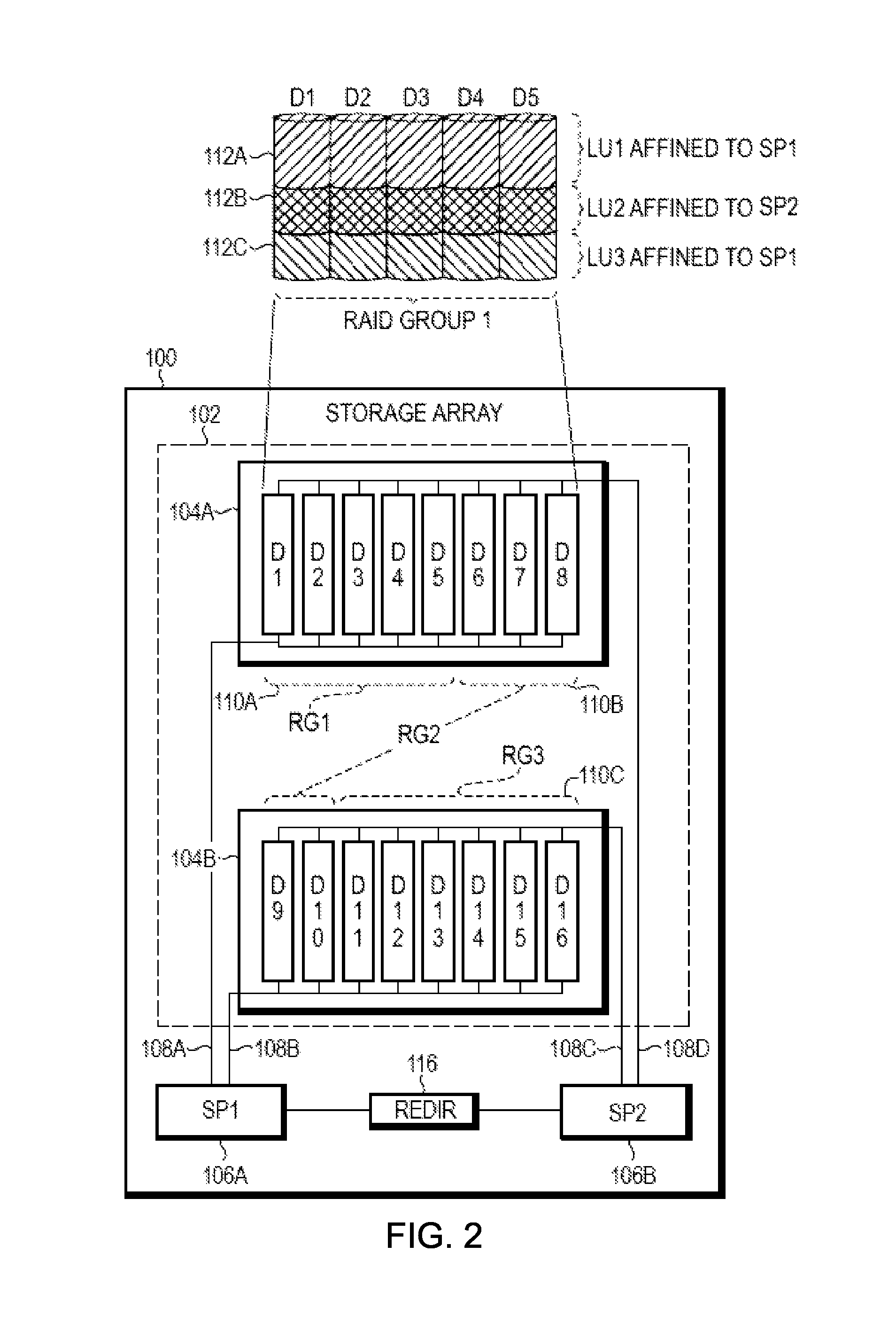
[0018]Generally, a storage pool is a collection of storage that is provisioned for a logical unit. A storage pool may be a collection of disks, which may include disks of different types. Storage pools may further be subdivided into slices; for example a 1 gigabyte (GB) slice may be the allocation element for a logical unit. Further, a slice may be 256 megabytes (MB) in size. A pool may include a set of storage tiers. Further, both a storage tier and a pool may have storage devices of different performance capabilities and costs. A slice may be considered the smallest element that can be tracked and moved. It may be advantageous to store the hot or most accessed data on the devices within the storage pool with the best performance characteristics while storing the cold or least accessed data on the devices that have slower performance characteristics. This can lead to a lower cost system having both faster and slower devices that can emulate the performance of a more expensive syst...


PUM


Abstract

A technique is used for optimizing data location in data storage arrays. A primary storage array is associated with a secondary storage array, the primary storage array and secondary storage array including auto-tiering functionality, where the secondary storage array is configured as a backup storage array for the primary storage array. Tiering metadata is derived for a storage object stored on the primary storage array. The tiering metadata is transmitted to the secondary storage array. Auto-tiering is initiated at the secondary storage array, where the received tiering metadata is provided as input to the secondary storage array's auto-tiering function when auto-tiering replicated storage object associated with the tiering metadata.

Description

BACKGROUND[0001]1. Technical Field[0002]This application relates generally to optimizing data location in data storage arrays.[0003]2. Description of Related Art[0004]A traditional storage array (herein also referred to as a “data storage system,”“disk storage array,”“disk array” or simply “array”) is a collection of hard disk drives operating together logically as a unified storage device. Storage arrays are designed to store large quantities of data. Storage arrays typically include one or more storage array processors (SPs), for handling requests for allocation and input / output (I / O) requests. An SP is the controller for and primary interface to the storage array.[0005]A storage array may be thought of as a system for managing a large amount of a resource, i.e., a large number of disk drives. Management of the resource may include allocation of a portion of the resource in response to allocation requests. In the storage array example, portions of the storage array may be allocate...

Claims


Application Information

Patent Timeline
IPC IPC(8): G06F11/00G06F3/06G06F11/14
CPCG06F3/0644G06F3/0617G06F3/065G06F3/0683G06F11/1469G06F11/2094G06F11/2092G06F2212/286G06F2212/262G06F2212/466G06F11/1076G06F12/0868G06F2212/1016G06F3/0649G06F3/067G06F3/061G06F3/0685
Inventor CHEN, XIANGPINGDE FOREST, MILES A.DUPREY, DENNIS T.OWEN, KARL M.BONO, JEAN-PIERREO'BRIEN, III, WALTER A.
Owner EMC IP HLDG CO LLC
Why Eureka
Try Eureka