
Method and device for controlling a powertrain

a technology of powertrain and control signal, applied in the direction of electric generator control, dynamo-electric converter control, dynamo-electric gear control, etc., to achieve the effect of avoiding the saturation of control signal

Active Publication Date: 2016-10-11
RENAULT SA
View PDF19 Cites 0 Cited by
  • Summary
  • Abstract
  • Description
  • Claims
  • Application Information

AI Technical Summary

Benefits of technology

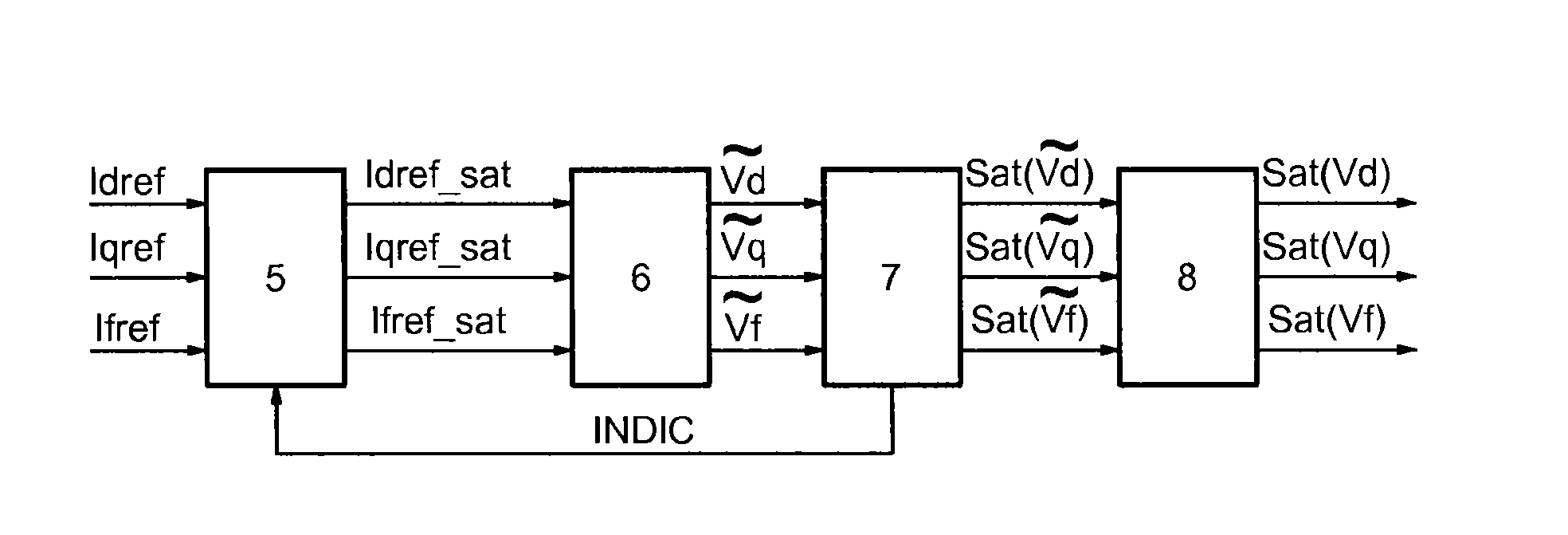
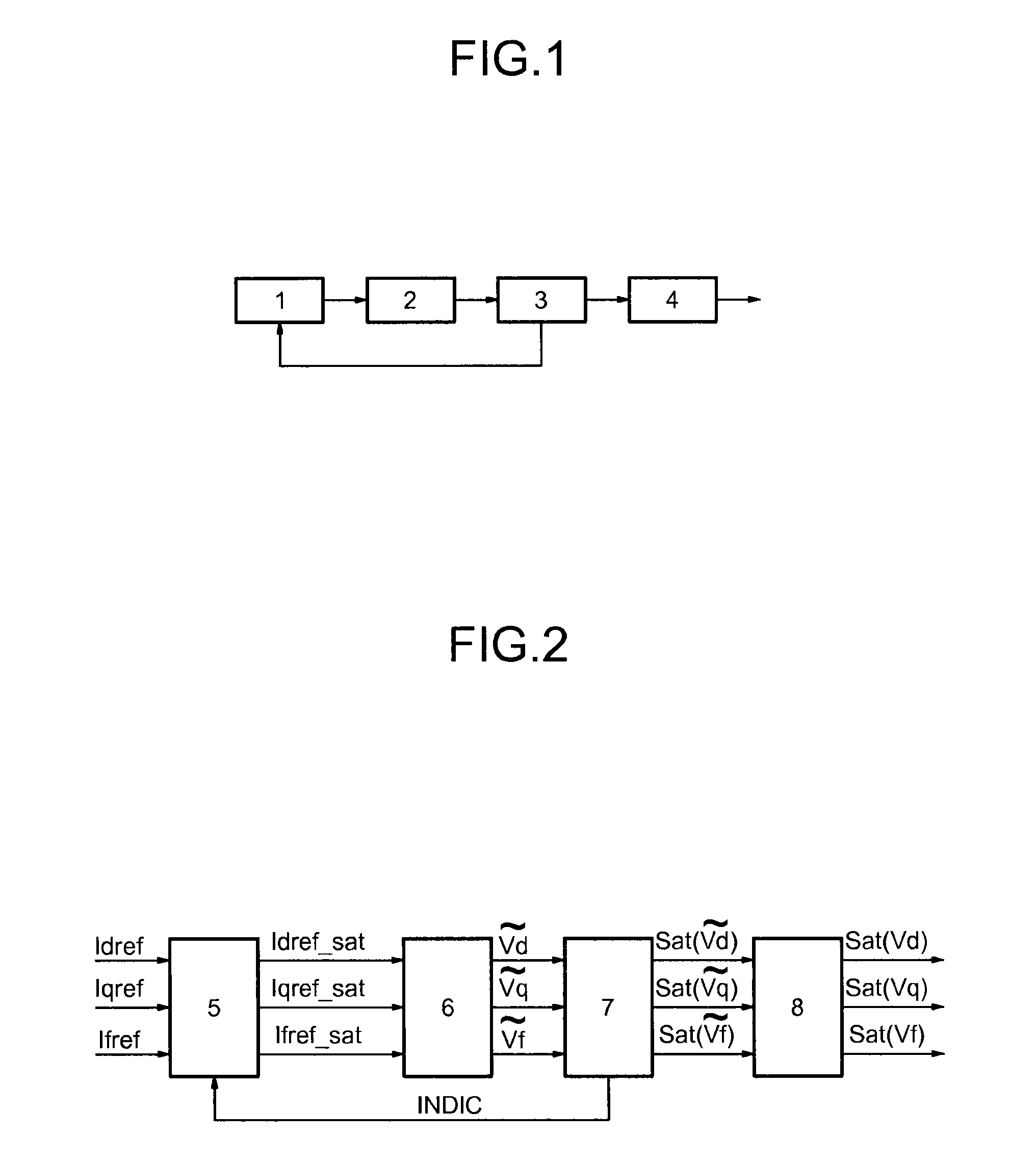
The present invention is to improve the quality of regulation of an electric motor by maintaining decoupling between the control of the rotor and that of the stator during saturation. This allows for better tracking of the desired wheel torque. The control method is stable and efficient, with the advantage of a total decoupling between the rotor and stator current setpoints that keeps the system in control even during saturation. The saturation strategy ensures stability by performing peak-clipping in the decoupled space, and the recalculation of current setpoints in the event of saturation enables stable current values even if the setpoints cannot be reached. The control signals can also be blocked to avoid saturation. Overall, this invention provides a more effective and efficient way to control an electric motor.

Problems solved by technology

However, there is no provision in the prior art of a saturation making it possible to maintain a dynamic decoupling of the controls.

Method used


Image

  • Method and device for controlling a powertrain
  • Method and device for controlling a powertrain
  • Method and device for controlling a powertrain

Examples


Embodiment Construction

[0029]To assure the regulation of a power train comprising a synchronous motor comprising a stator and a rotor and installed in a vehicle, an inverter is used that makes it possible to control the voltage of the stator phases and a chopper for controlling the rotor voltage. These two devices are powered by a battery installed in the vehicle.

[0030]A Park reference frame is also used, which makes it possible to express the electrical quantities in a revolving reference frame for example linked to the rotor in the case of a synchronous motor. This reference frame comprises three axes: d, q and f. The axes d and q are associated with the stator and the axis f is associated with the rotor. The control signals for the electric motor Vd, Vq, Vf and the current setpoints applied Id Iq If correspond to the components of a control signal and of a current respectively along the axes: d, q, f.

[0031]In the Park reference frame, a power train comprising a synchronous motor is governed by the foll...


PUM


Abstract

A method controlling a powertrain fitted in an automobile and including an electric motor including a rotor and stator, the method including: regulation of currents of the rotor and the stator via control signals from the electric motor, wherein the currents and control signals are expressed in a rotating coordinate system and include a plurality of axes, the control signals resulting from a first transformation including a change of variable that enables dynamic decoupling between the control signals, along each of the axes of the plurality of axes; saturation of the control signals resulting from the first transformation to satisfy constraints of a battery fitted in the automobile and connected to the electric motor; and blockage of at least some of the current reference values of the regulation if the control signals are saturated.

Description

BACKGROUND[0001]The technical field of the invention is the control of electric motors, and in particular the control of the electric motors of wound rotor synchronous type.[0002]An electric motor of wound rotor synchronous type comprises a fixed part called stator and a moving part called rotor. The stator comprises three windings offset by 120° and powered by alternating current. The rotor comprises one winding powered by direct current.[0003]The currents of the phases of the stator depend on the resistances and inductances of the rotor and of the stator as well as on the mutual inductance between the rotor and the stator.[0004]The control of such a system requires account to be taken of the control saturation phenomena, due in particular to the voltage limits of the battery.[0005]The document U.S. Pat. No. 3,851,234 discloses a method for avoiding the magnetic saturation by reducing the speed of the motor or the torque supplied.[0006]The document U.S. Pat. No. 5,015,937 discloses...

Claims


Application Information

Patent Timeline
IPC IPC(8): B60L15/20H02P21/00H02P21/05H02P101/45
CPCH02P21/0085H02P21/05H02P25/024B60L15/20H02P21/0003H02P21/0021H02P2101/45H02P2207/05Y02T10/7258Y02T10/72
Inventor MERIENNE, LUDOVICMALOUM, ABDELMALEK
Owner RENAULT SA
Learn More