
High-frequency module and communication device

a communication device and high-frequency technology, applied in the direction of transmission, electrical equipment, etc., can solve the problems of lowering the reception sensitivity and the like of another communication system, and the difficulty of obtaining sufficient attenuation of the second-order harmonic of the lte-band, so as to improve the reception sensitivity of the receiver and reduce the reception sensitivity

Active Publication Date: 2016-10-11
MURATA MFG CO LTD
View PDF15 Cites 2 Cited by
  • Summary
  • Abstract
  • Description
  • Claims
  • Application Information

AI Technical Summary

Benefits of technology

The solution effectively reduces harmonic signal levels and stabilizes harmonic characteristics, improving reception sensitivity by preventing harmonics from reaching receivers in adjacent frequency bands, such as GPS receivers.

Problems solved by technology

In the case where a frequency band of the harmonic is used by another communication system, this may pose a problem of lowering reception sensitivity and the like of another communication system.
Thus, it is difficult to obtain sufficient attenuation of the second-order harmonic of LTE-Band 13 with a reception filter provided in a GPS receiver.

Method used


Image

  • High-frequency module and communication device
  • High-frequency module and communication device
  • High-frequency module and communication device

Examples


Embodiment Construction

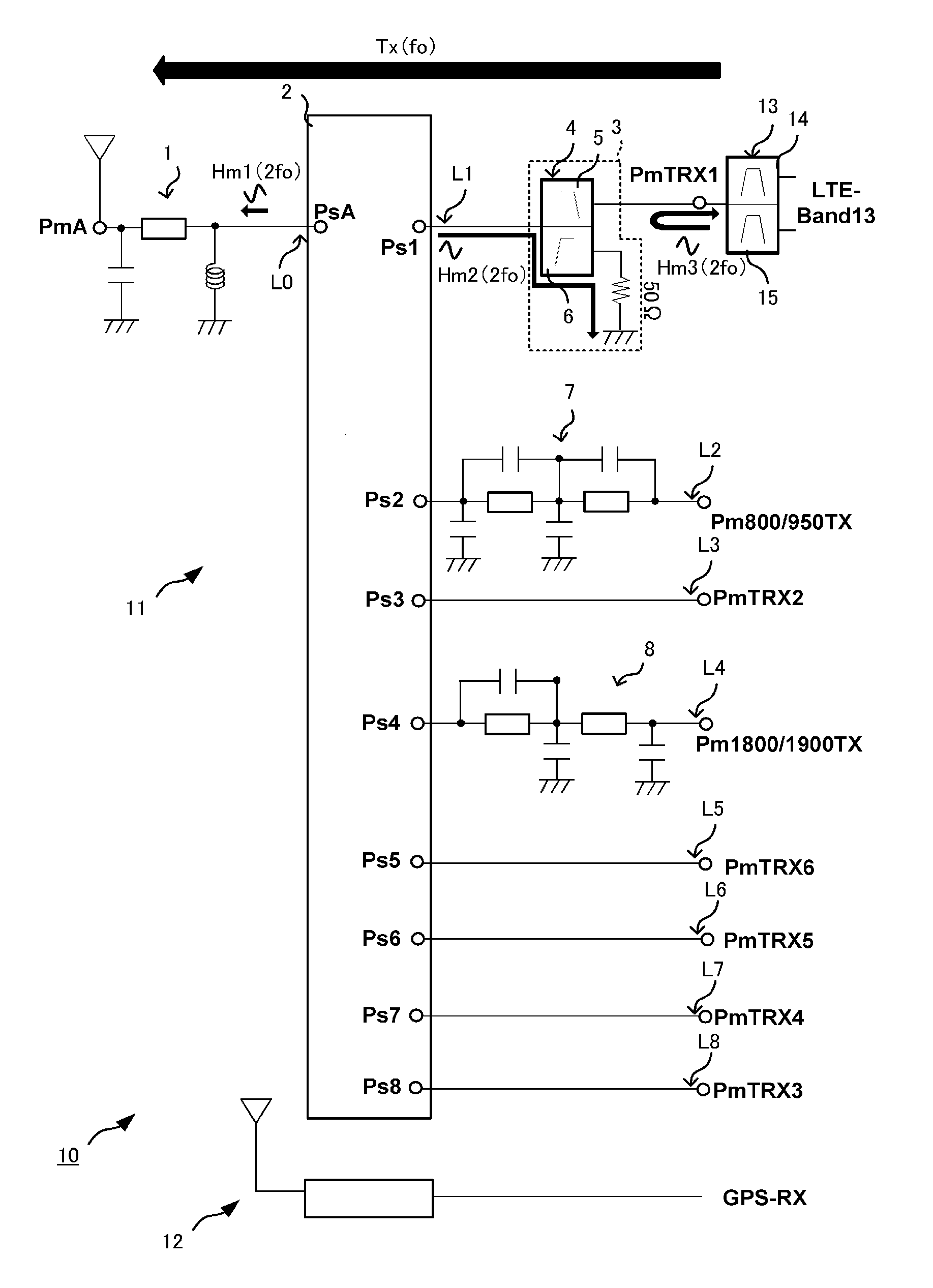
[0027]First, a high-frequency module and a communication device according to a first preferred embodiment of the present invention are described.

[0028]FIG. 1 is a schematic circuit diagram of a communication device according to the first preferred embodiment.

[0029]A communication device 10 depicted in FIG. 1 includes a high-frequency module 11, a GPS receiver 12, a duplexer 13, and a plurality of transceiver circuits that are not illustrated.

[0030]The communication device 10 performs wireless communications using a plurality of communication methods. The high-frequency module 11 is connected between a single antenna and a transmitter circuit or a receiver circuit in a subsequent stage, which is not illustrated. The high-frequency module 11 has the capability of transmitting and receiving transmitting signals and receiving signals corresponding to the plurality of communication methods using the single antenna as a common antenna. The GPS receiver 12 includes its own antenna and rece...


PUM


Abstract

A high-frequency module is connected to a switch port and a switch IC including an antenna connection port and a plurality of switch ports. The high-frequency module includes a signal path that outputs transmitting signals having a predetermined frequency band to the switch IC, a module port connected to the signal path and to which a duplexer and a transmitter circuit are connected, and a harmonic branch circuit that is provided on the signal path and allows a harmonic of the transmitting signal to escape to ground.

Description

BACKGROUND OF THE INVENTION[0001]1. Field of the Invention[0002]The present invention relates to high-frequency modules provided in antenna front-ends of wireless communication devices such as cellular phones and to communication devices each including a high-frequency module and a receiver that is separately provided in addition to the high-frequency module.[0003]2. Description of the Related Art[0004]FIG. 5 is a circuit diagram of a high-frequency module according to an exemplary prior art (for example, see Japanese Unexamined Patent Application Publication No. 2007-129459) to be used in an antenna front-end of a cellular phone and the like. A high-frequency module 101 includes a switch IC 102, a duplexer 103, and a duplexer 104. The high-frequency module 101 has the capability of transmitting and receiving signals in a first communication band and a second communication band using a transmission / reception antenna Ant1. The switch IC 102 includes an antenna connection port PsA1 an...

Claims


Application Information

Patent Timeline
Patent Type & Authority Patents(United States)
IPC IPC(8): H04B1/44H04B1/52H04B1/00H04B1/3805H04B1/403
CPCH04B1/52H04B1/006H04B1/0057H04B1/0064H04B1/3805H04B1/406
Inventor UEJIMA, TAKANORI
Owner MURATA MFG CO LTD
Learn More