Wireless charging method and system, and mobile terminal
a wireless charging and mobile terminal technology, applied in the field of mobile communication technologies, can solve the problems of limited solution that performs wired charging with usb, inability to efficiently deal with matters, etc., and achieve the effect of reducing usage limitations and simple operation
- Summary
- Abstract
- Description
- Claims
- Application Information
AI Technical Summary
Benefits of technology
Problems solved by technology
Method used
Image
Examples
embodiment 1
[0075
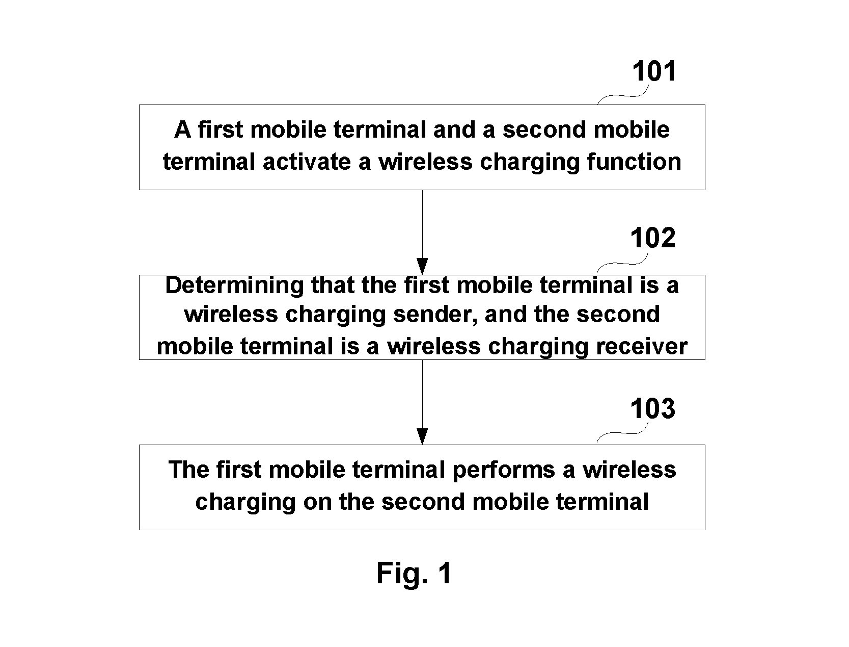
[0076]This embodiment of the present application provides a wireless charging method. FIG. 1 is a flow diagram of a wireless charging method according to Embodiment 1 of the present application. As illustrated in FIG. 1, the wireless charging method includes:
[0077]Step 101: a first mobile terminal and a second mobile terminal activate a wireless charging function.
[0078]Step 102: determining that the first mobile terminal is a wireless charging sender, and the second mobile terminal is a wireless charging receiver.
[0079]Step 103: the first mobile terminal performs a wireless charging on the second mobile terminal.
[0080]In this embodiment, the first mobile terminal and the second mobile terminal may be mobile communication terminal (e.g., cellular phone); tablet PC, digital camera, notebook computer, etc.; or wearable devices such as Google glass, iwatch, etc. The present application is not limited thereto, and hereinafter descriptions are given through an example where both the ...
embodiment 2
[0133
[0134]This embodiment of the present application provides a mobile terminal, which is corresponding to the wireless charging method in Embodiment 1, and the same contents are omitted herein. FIG. 6 is a construction diagram of a mobile terminal according to Embodiment 2 of the present application. For the purpose of convenience, other members of the mobile terminal are not illustrated in FIG. 6.
[0135]As illustrated in FIG. 6, the mobile terminal 600 includes a battery 601 configured to store electric energy; a master controller 602 configured to control the mobile terminal 600; and a wireless charging transmitting circuit 603 configured to wirelessly charge the electric energy stored in the battery 601 into another mobile terminal, according to a control instruction from the master controller 602. For example, the master controller 602 may include various hardware and / or software components, such as those described below with respect to the mobile terminal 900. For example, the...
embodiment 3
[0158
[0159]This embodiment of the present application provides a wireless charging system, and contents the same as those in Embodiments 1 and 2 are omitted herein.
[0160]FIG. 10 is a construction diagram of a wireless charging system according to Embodiment 3 of the present application. As illustrated in FIG. 10, the wireless charging system 1000 includes:
[0161]a first mobile terminal 1001 configured to serve as a wireless charging sender; and
[0162]at least one second mobile terminal 1002 configured to serve as a wireless charging receiver.
[0163]In this embodiment, the first mobile terminal 1001 may be any of mobile terminals 600 to 900 in Embodiment 2; the second mobile terminal 1002 may also be any of mobile terminals 600 to 900 in Embodiment 2, or an existing mobile terminal capable of receiving a wireless charging. For example, there may be one or more second mobile terminals 1002. For example, the first mobile terminal 1001 may simultaneously perform a wireless charging on more...
PUM
 Abstract
Description
Claims
Application Information
 - R&D
- Intellectual Property
- Life Sciences
- Materials
- Tech Scout
- Unparalleled Data Quality
- Higher Quality Content
- 60% Fewer Hallucinations
Browse by: Latest US Patents, China's latest patents, Technical Efficacy Thesaurus, Application Domain, Technology Topic, Popular Technical Reports.
© 2025 PatSnap. All rights reserved.Legal|Privacy policy|Modern Slavery Act Transparency Statement|Sitemap|About US| Contact US: help@patsnap.com


