Pipe insulation apparatus having finishing cover of compression-bonded structure

a technology of pipe insulation and compression bonding, which is applied in the direction of thermal insulation, pipe protection, pipe protection by thermal insulation, etc., can solve the problems of low degree of accuracy, waste of enormous amount of materials, and thin walls of pipes, so as to improve the degree of connection accuracy, reduce the effect of waste of materials and labor costs

Active Publication Date: 2016-10-25
DONG IN ENG
View PDF17 Cites 8 Cited by
  • Summary
  • Abstract
  • Description
  • Claims
  • Application Information

AI Technical Summary

Benefits of technology

[0017]According to the present invention, attachment and detachment are easy, and it is possible to improve a degree of connection accuracy, and it is possible to achieve process simplification. Also, it is possible to improve the rigidity of finishing covers and enhance the connection strengths of the connection portions. As a result, it is possible to improve the rigidity of the pipe insulation apparatus.

Problems solved by technology

With time, these pipes are corroded due to high-temperature and high-pressure steam, whereby the walls of the pipes are thinned.
Such thinning of the walls of pipes may cause pinholes in the pipes with time, resulting in nasty accidents.
This manner in which insulators are applied after wall thinning inspection causes a huge amount of waste such as insulators and finishing covers, which results in a waste of an enormous amount of materials.
However, a process of manufacturing the finishing covers having the above described structure requires a process of bending and connecting the end portions of the assembly segments and the end portions of the reinforcing connectors, and thus is complicated and has a low degree of accuracy, and the reinforcing connectors and the assembly end portions are frequently separated, resulting in defects.

Method used


Image

  • Pipe insulation apparatus having finishing cover of compression-bonded structure
  • Pipe insulation apparatus having finishing cover of compression-bonded structure
  • Pipe insulation apparatus having finishing cover of compression-bonded structure

Examples


Embodiment Construction

[0029]Hereinafter, embodiments of the present invention will be described in detail with reference to the accompanying drawings only for the purpose of providing a thorough understanding of the present invention to those skilled in the art.

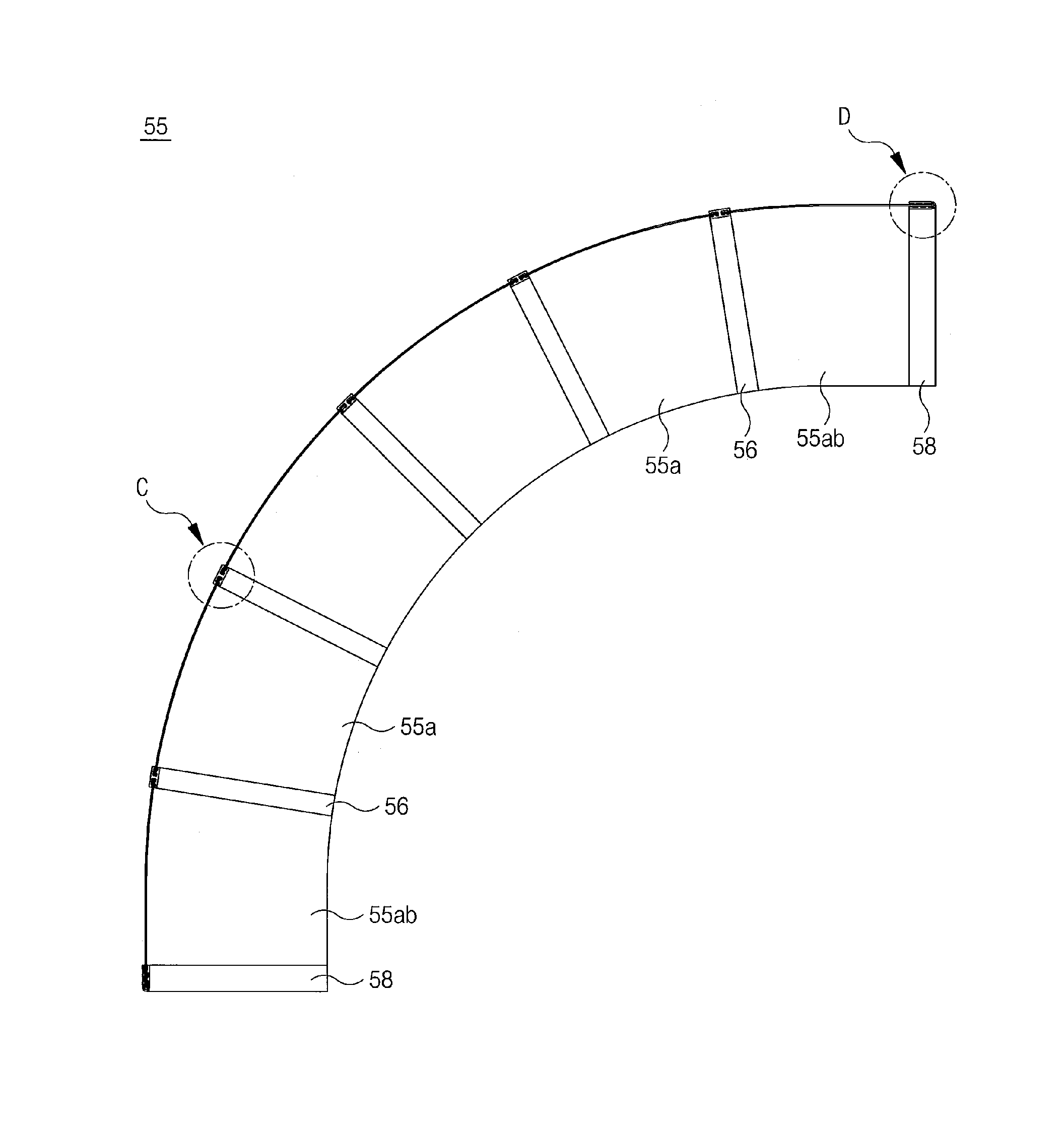
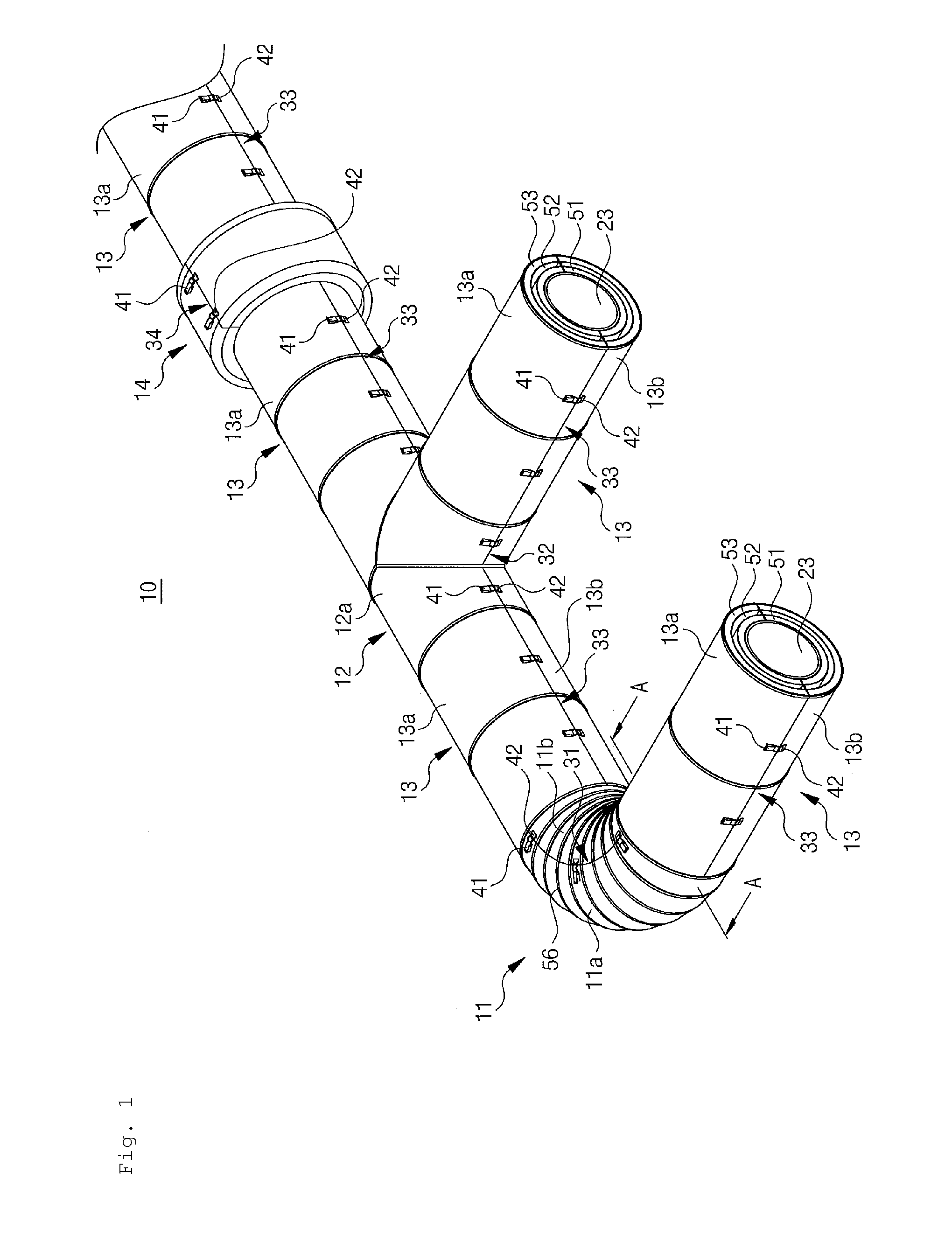
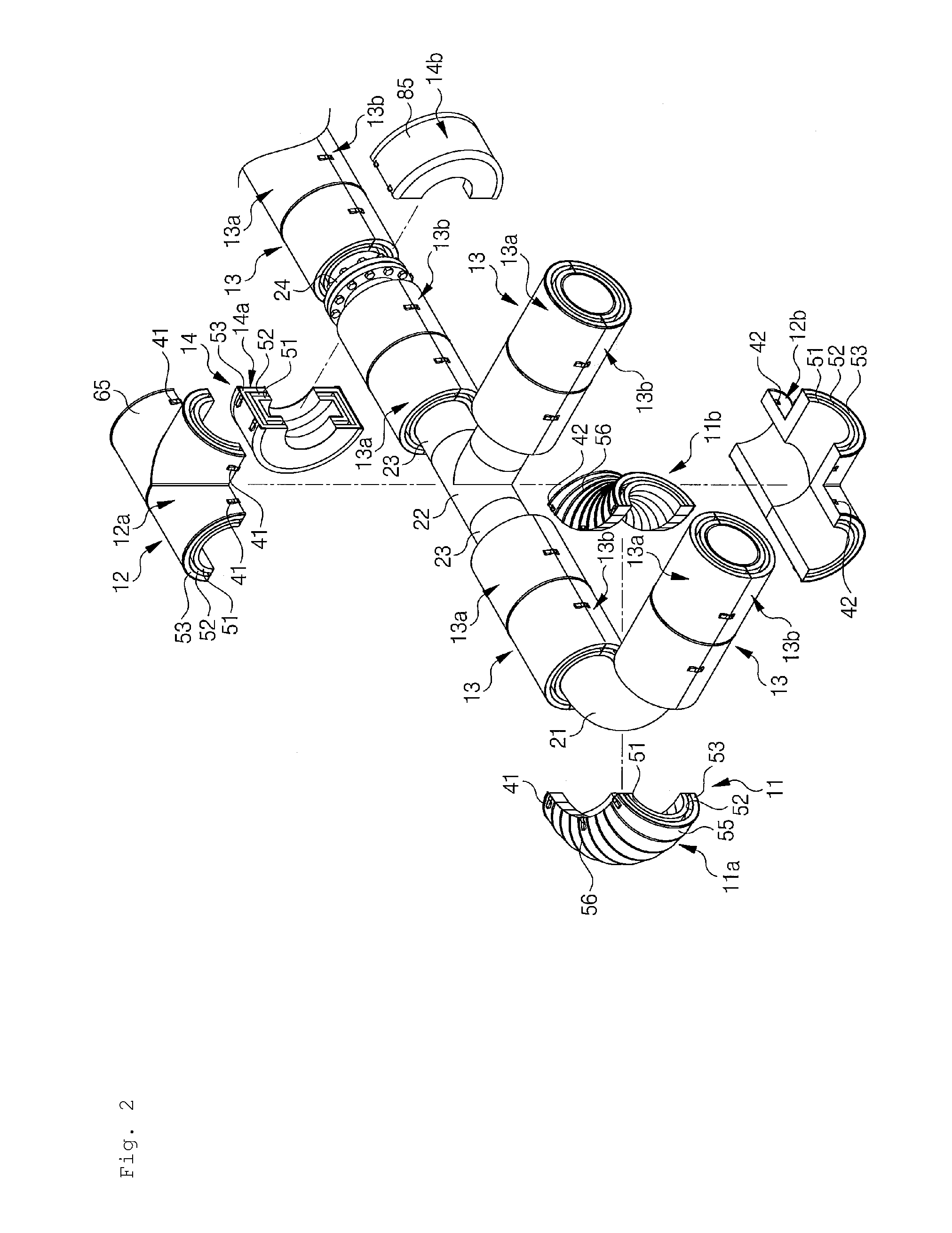
[0030]FIGS. 1 to 4 are views illustrating a pipe insulation apparatus according to an embodiment of the present invention. FIG. 1 is a perspective view illustrating an assembled state of the pipe insulation apparatus according to the embodiment of the present invention, and FIG. 2 is a view illustrating a state where an elbow insulation unit, a T-joint insulation unit, and a flange insulation unit of FIG. 1 have been disassembled, and FIG. 3 is a view illustrating a state where straight-pipe insulation units of FIG. 1 have been disassembled, and FIG. 4 is a cross-sectional view along a line A-A of FIG. 1.

[0031]As shown in FIGS. 1 to 4, a pipe insulation apparatus 10 according to an embodiment of the present invention is easily attached to and deta...


PUM


Abstract

In a pipe insulation apparatus includes a plurality of segments which are connected so as to be separable along division lines, and each of the plurality of segments is composed of a plurality of insulation layers, and is covered by a finishing cover. The finishing cover includes: at least one joint chassis that is made of a soft metal material, and has a first insertion groove and a second insertion groove formed at a first end portion and a second end portion, respectively, and has a saw-toothed first protrusion formed on one inner side surface of each of the first insertion groove and the second insertion groove and a saw-toothed second protrusion formed alternately with the first protrusion on the other inner side surface; and a plurality of plates that is made of a soft metal material.

Description

TECHNICAL FIELD[0001]The present invention relates to a pipe insulation apparatus having finishing covers of compression-bonded structure, and more specifically, to a pipe insulation apparatus which includes finishing covers of compression-bonded structure, and is capable of process simplification during manufacturing of finishing covers for a pipe insulation apparatus, and can improve rigidity and accuracy.BACKGROUND ART[0002]In general, in power plants (such as nuclear power plants and thermal-electric power plants), petrochemical plants, and the like, pipes for transferring high-temperature and high-pressure steam are installed. With time, these pipes are corroded due to high-temperature and high-pressure steam, whereby the walls of the pipes are thinned.[0003]Such thinning of the walls of pipes may cause pinholes in the pipes with time, resulting in nasty accidents. For this reason, once a year, planned maintenance is performed, whereby wall thinning inspection is performed on p...

Claims


Application Information

Patent Timeline
Patent Type & Authority Patents(United States)
IPC IPC(8): F16L9/14F16L59/16F16L59/22F16L59/18F16L59/11F16L59/10F16L59/02
CPCF16L59/163F16L59/024F16L59/103F16L59/11F16L59/161F16L59/184F16L59/22F16L59/10F16L59/147
Inventor KIM, KOOK SOO
Owner DONG IN ENG
Why Eureka
Try Eureka