Supercharge Your Innovation With Domain-Expert AI Agents!

Method for determining a closed trajectory by means of a laser and a laser light sensor and apparatus for determining a closed trajectory

a laser light sensor and closed trajectory technology, applied in the direction of instruments, measurement devices, using optical means, etc., can solve problems such as inability to determine closed trajectory

Active Publication Date: 2016-10-25
PRUTECHNIK DIETER BUSCH AG
View PDF21 Cites 1 Cited by
  • Summary
  • Abstract
  • Description
  • Claims
  • Application Information

AI Technical Summary

Benefits of technology

Enables high-accuracy alignment of a reference axis relative to a center axis even in situations where inclination angle measurement is not possible or is inaccurate, reducing errors and improving precision in applications like turbine alignment.

Problems solved by technology

For the determination of the alignment of essentially vertically aligned bores or openings, it is not possible—owing to the principle of measurement—to use an inclinometer or else not possible to use it with sufficient accuracy.

Method used


Image

  • Method for determining a closed trajectory by means of a laser and a laser light sensor and apparatus for determining a closed trajectory
  • Method for determining a closed trajectory by means of a laser and a laser light sensor and apparatus for determining a closed trajectory
  • Method for determining a closed trajectory by means of a laser and a laser light sensor and apparatus for determining a closed trajectory

Examples


Embodiment Construction

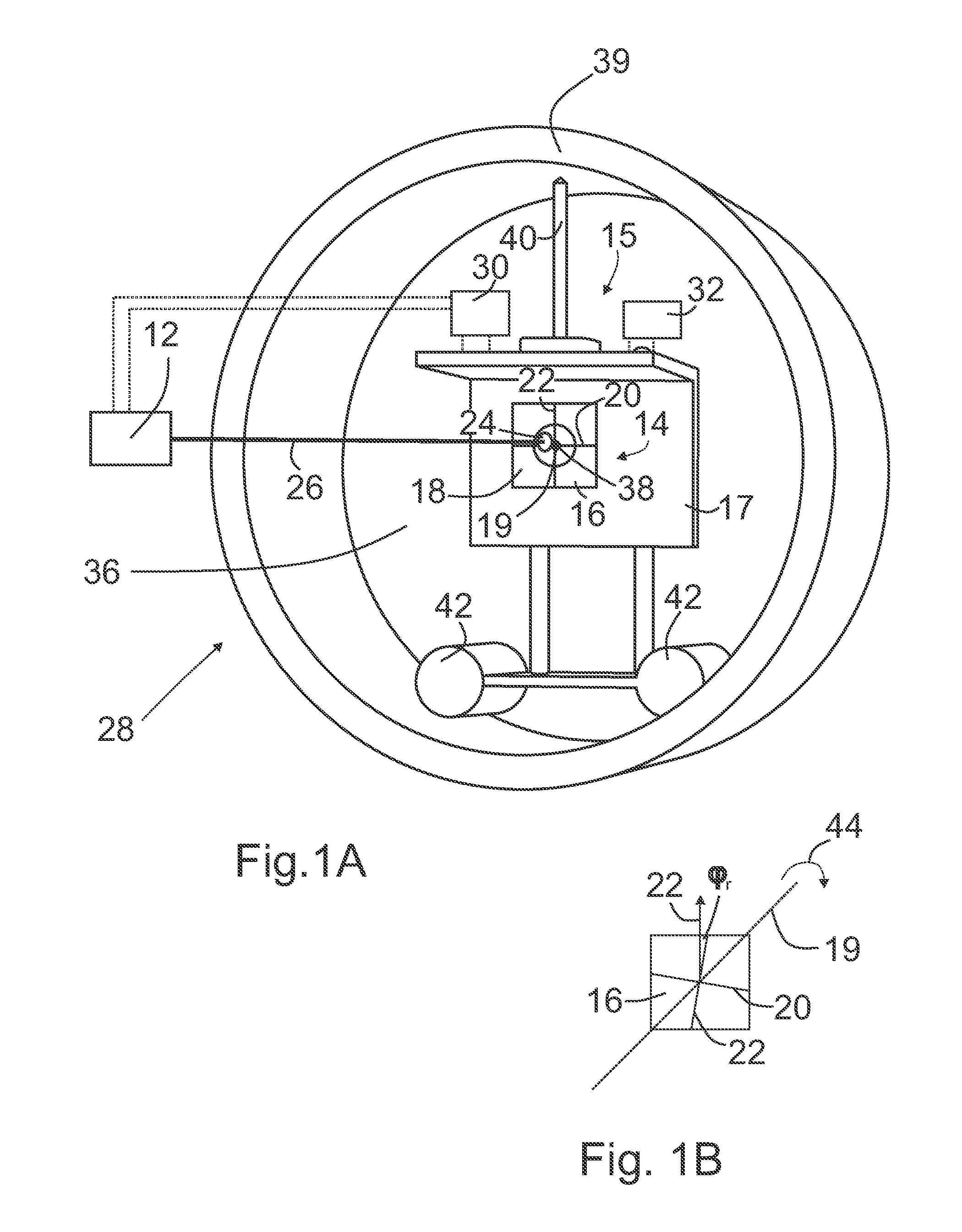
[0062]The apparatus 28 for determining a closed trajectory curve comprises a laser 12, a laser light sensor 14 having a flat field of view 16, a holding device 17, and an analysis unit 32.

[0063]The field of view 16 has a coordinate system 18 with an X coordinate axis 20 and a Y coordinate axis 22 that is at a right angle to the X coordinate axis 20.

[0064]The laser light sensor 14 is set up so as to record the X coordinate and Y coordinate of the position of the laser light spot 24 on the field of view 16 of the laser light beam 26 that can be generated by the laser 12 and impinges on the field of view 16.

[0065]The field of view 16 is attached to the holding device 17 in a movable manner in such a way that the field of view 16 can be conveyed into a first position and into further positions on the holding device 17, in which the X coordinate axis 20 and the Y coordinate axis 22 are oriented at a right angle to the center axis 38 (symbolized in FIG. 1A only very schematically by a bla...


PUM


Abstract

The invention relates to a method for determining a closed trajectory curve (10) by laser (12) and a laser light sensor (14) having a flat field of view (16), wherein the method comprises the steps A to E. The invention further relates to an apparatus for determining a closed trajectory curve (10).

Description

BACKGROUND OF THE INVENTION[0001]The present invention relates to a method for determining a closed trajectory by means of a laser and a laser light sensor as well as an apparatus for determining a closed trajectory.[0002]Methods and apparatuses of the kind mentioned in the introduction are used, in particular, for methods of measurement that are intended to determine the position of a rectilinear reference direction or reference axis relative to the position of the center axis or axis of symmetry of a circular cylindrical bore or opening of a body or of an apparatus in order to bring this bore or opening into alignment with another bore, for example, the center axis of which then represents the reference axis. For this, the laser is aligned such that the laser light beam of the laser can be aligned coincidentally with the reference axis. Furthermore, the laser light sensor is arranged in a defined position in the bore and a flat field of view of the laser light sensor is arranged p...

Claims


Application Information

Patent Timeline
Patent Type & Authority Patents(United States)
IPC IPC(8): G01B11/22G01B11/12G01B11/26G01B11/27
CPCG01B11/12G01B11/26G01B11/272
Inventor LOCOGE, PASCALZOCKE, CHRISTINE
Owner PRUTECHNIK DIETER BUSCH AG
Features
  • R&D
  • Intellectual Property
  • Life Sciences
  • Materials
  • Tech Scout
  • Unparalleled Data Quality
  • Higher Quality Content
  • 60% Fewer Hallucinations
Learn More