Paint booth filter

a filter and paint booth technology, applied in the field of filters, can solve the problems of affecting the effect of unable to meet the more strict environmental standards. achieve the effect of high holding capacity and maximum paint retention and depth loading

Active Publication Date: 2016-11-01
COLUMBUS INDS
View PDF22 Cites 8 Cited by
  • Summary
  • Abstract
  • Description
  • Claims
  • Application Information

AI Technical Summary

Benefits of technology

[0015]The layers of paper can differ from the front to the back of the filter, such as by the sizes of the holes in the paper, the solid material between the holes, the shapes of the holes and / or the positions of the holes relative to the solid portions. This can thereby allow one to create a filter of ever decreasing hole size, offset holes, etc. to maximize paint retention and depth loading for high holding capacity. In one contemplated embodiment, a frame and sleeve combination placed in the most upstream position has the largest holes, the next downstream frame and sleeve combination has smaller holes, and so forth to the back of the housing where air exits at the downstream end.

Problems solved by technology

An inertia filter causes turbulence in the flow of gas that contains the paint particles, thereby projecting the suspended particles against the walls of the filters due to the particles' inability to flow around the walls of the filters as well as air.
Inertia filters ensure a constant pressure drop over their lifetime but have the drawback that they do not retain small, light particles, the mass of which is insufficient for inertia to project them against the walls for deposition.
For certain types of paint, particularly lacquers, these filters have an efficiency that cannot satisfy the more strict environmental standards.
These filters typically do not retain dry particles having a size smaller than their pores.
Thus, screening filters commonly have a low efficiency.
It is possible to make such filters with smaller pores to increase efficiency, but this introduces a substantial pressure drop across the media.
Loading with particulate causes such screening filters to clog rapidly, thereby causing an increasing pressure drop, necessitating frequent replacement.

Method used


Image

  • Paint booth filter
  • Paint booth filter
  • Paint booth filter

Examples


Embodiment Construction

[0030]U.S. Provisional Application No. 61 / 792,956 filed Mar. 15, 2013 is incorporated in this application by reference.

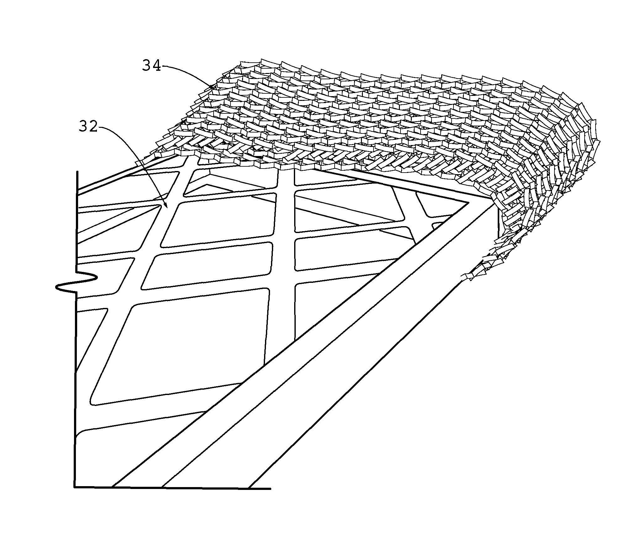
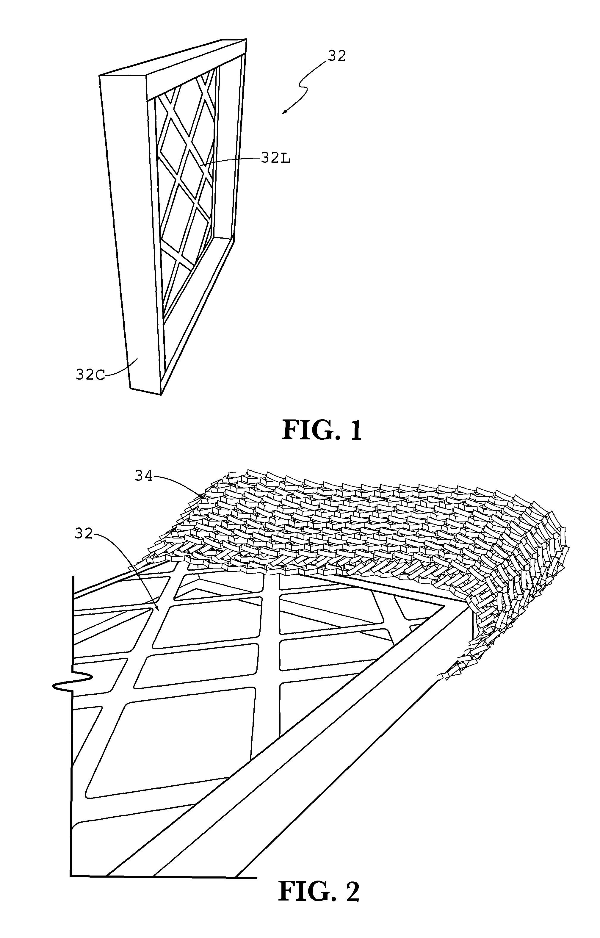
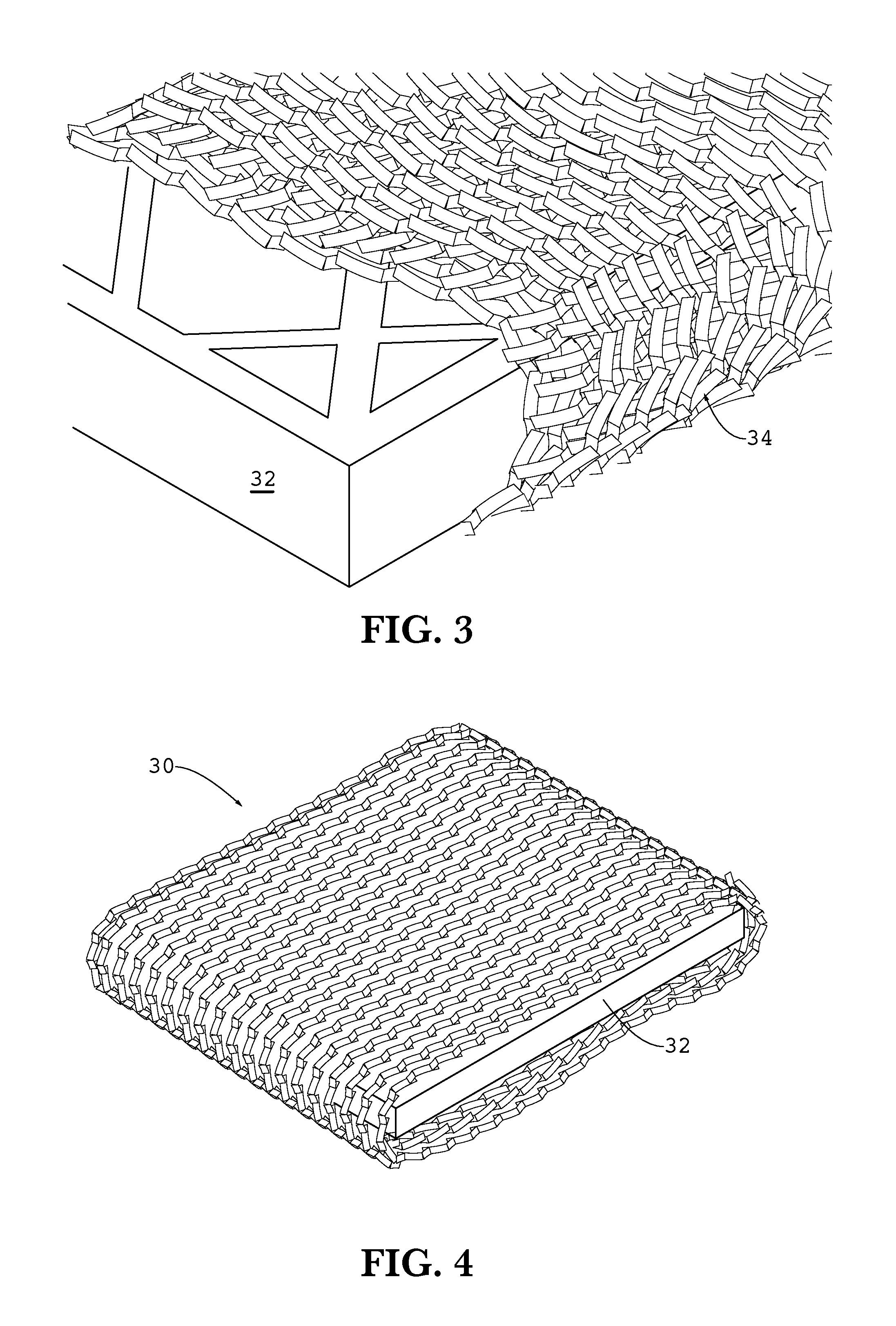
[0031]The filter 10 shown in FIGS. 9 and 10 has a housing 12 made up of a peripheral wall 14, which extends around the entire periphery of the filter, and opposing filter-retaining screens 20 and 22 (screen 22 is not visible in FIGS. 9 and 10). The filter-retaining screen 20 forms the upstream face, and the screen 22 forms the downstream face, of the filter. Both the peripheral wall 14 and the filter-retaining screens 20 and 22 are preferably made of paperboard, corrugated paper, plastic or any other suitable material that remains rigid enough to retain its shape under the circumstances in a paint booth filtration system. The screens are shown with a diamond shape oriented vertically, but it should be noted that any shape opening and pieces connecting across the housing can be used to retain the filter elements. No specific shape is critical, so long as the shape us...


PUM

PropertyMeasurementUnit
thicknessaaaaaaaaaa
thicknessaaaaaaaaaa
thicknessaaaaaaaaaa

Abstract

The invention is a filter for paint booth filtration systems. The filter has a housing made up of a peripheral wall, which extends around the entire periphery of the filter, and opposing filter-retaining screens. The filter-retaining screens form the upstream and downstream faces of the filter. The filtration element may be a frame with lattice and a rigidifying channel therearound combined with a filtration material extended around the frame. The filtration material may be slit and expanded paper that is joined at overlapping edges, or merely overlapped, to form a sleeve. One or more of the filtration elements are mounted in the housing substantially parallel to one another and to the screens.

Description

CROSS-REFERENCES TO RELATED APPLICATIONS[0001]This application claims the benefit of U.S. Provisional Application No. 61 / 792,956 filed Mar. 15, 2013. The prior application is hereby incorporated by reference.STATEMENT REGARDING FEDERALLY-SPONSORED RESEARCH AND DEVELOPMENT[0002](Not Applicable)THE NAMES OF THE PARTIES TO A JOINT RESEARCH AGREEMENT[0003](Not Applicable)REFERENCE TO AN APPENDIX[0004](Not Applicable)BACKGROUND OF THE INVENTION[0005]The invention relates generally to filters, and more particularly to filters made for applications where industrial coatings are applied.[0006]Paint, and other industrial coatings, are commonly applied to products in manufacturing facilities by spraying the products after placing the products in booths or stations that are separated from the rest of the manufacturing facility. Paint (which is a term used herein to include all industrial coatings) spraying creates “overspray” of atomized particles that do not adhere to the product's surface. S...

Claims


Application Information

Patent Timeline
Patent Type & Authority Patents(United States)
IPC IPC(8): B01D46/00B05B15/12B01D35/147B01D46/10
CPCB05B15/1248B01D46/0001B01D46/10Y10T29/49826B05B14/43
Inventor VICKERS, T. WAYNESLAMA, MOUNIR B. H.
Owner COLUMBUS INDS
Why Eureka
Try Eureka