
Magnetic wound closure device and method of use

a magnetic wound and magnetic technology, applied in the field of magnetic wound closure devices and methods of use, can solve the problems of scarring and infection, complex wound healing process, and delay in healing, so as to improve wound healing, reduce trauma, and improve wound healing

Active Publication Date: 2016-11-08
MOUSTAFA MOUSTAFA
View PDF10 Cites 11 Cited by
  • Summary
  • Abstract
  • Description
  • Claims
  • Application Information

AI Technical Summary

Benefits of technology

[0011]The present invention relates to a wound closure device and methods of reapproximating wound edges, which lead to improved wound healing. It is an object of the present invention to provide a magnetic wound closure device, such that when two of the magnetic wound closure devices are attached to skin on opposites sides of a wound, the magnets attract each other, thereby pulling together the edges of the wound. There are several advantages to the described invention, including: 1) placement of the device on a patient is faster than using staples or sutures, 2) no need to wait for an anesthetic, less trauma, 3) no painful injections are needed, 4) inspection of the wound is simple because the device is easily removable, and 5) the device can be easily manufactured in a variety of sizes and shapes that accommodate various wound sizes.
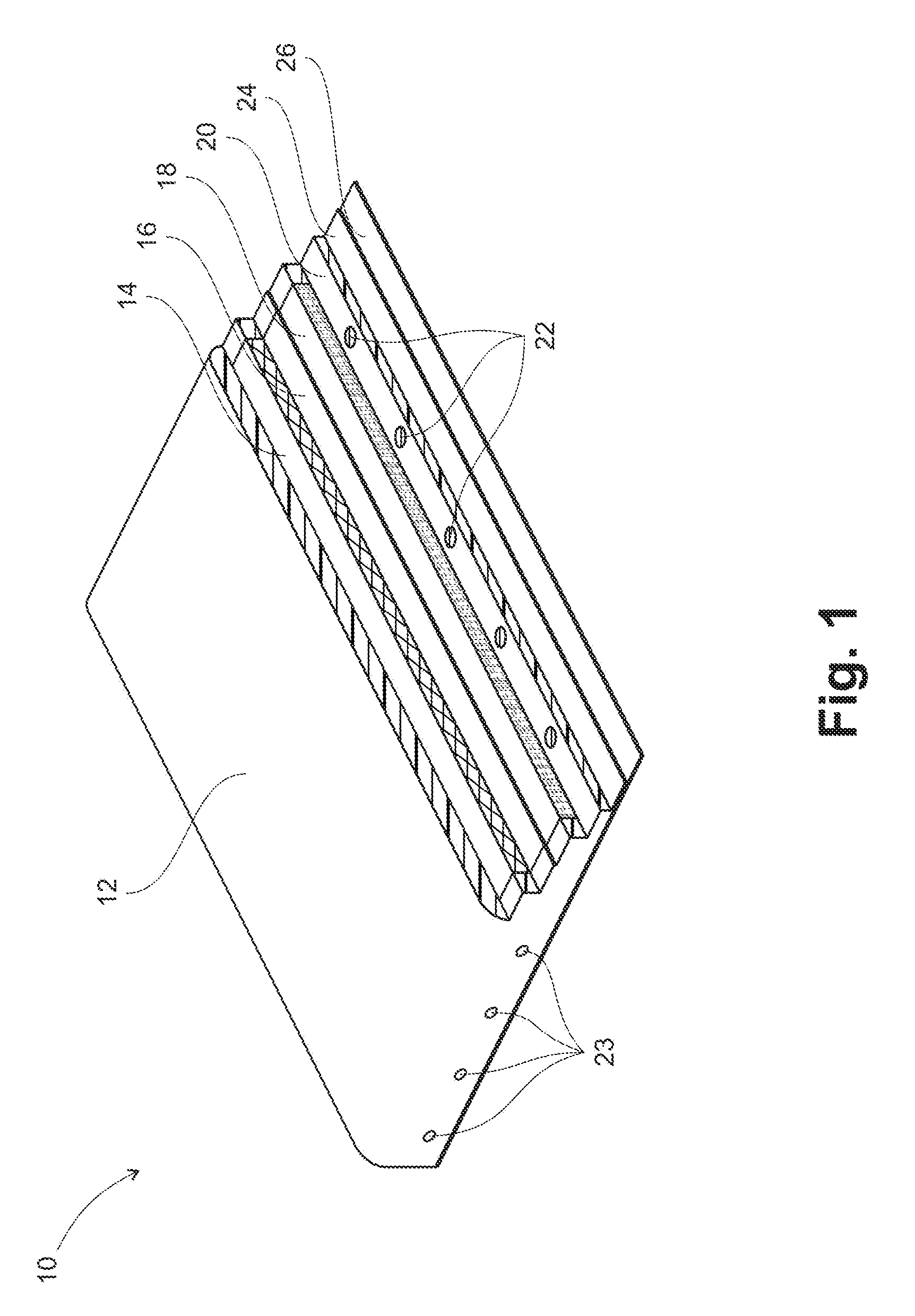
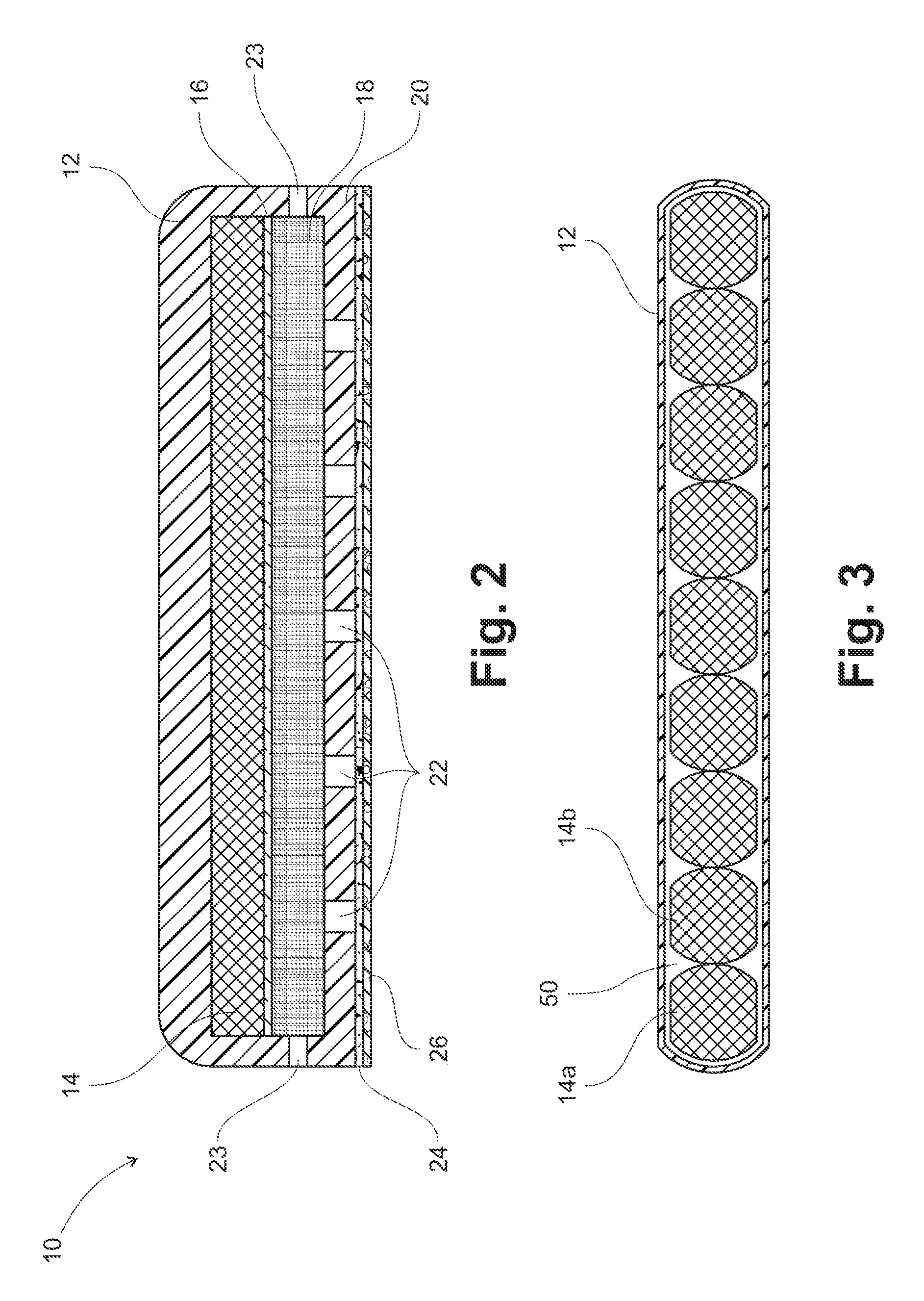
[0012]The magnetic wound closure device is used as a pair of magnetic wound closure devices aligned in opposite polarity with respect to each other so that the magnetic edges of each device attracts the polar opposite edge of another device. In one embodiment, each of the magnetic wound closure devices has a magnet, an insulation layer adjacent to the magnet, an absorbent layer adjacent to the insulation layer, a polymer layer that has a plurality of holes capable of draining wound secretions to and from the absorbent layer, and an adhesive layer adjacent to the bottom surface of the polymer layer. The adhesive layer allows the magnetic wound closure device to adhere to the surface of the skin of a patient. When placed on the patient, the interior edges of each magnet are oriented in opposite polarity to each other, and on opposite sides of a wound (with the wound situated below and between two magnetic closure devices). Since the two magnetic wound closure devices are attached to the skin of the patient via an adhesive layer, when the two magnetic wound closure devices draw toward each other due to the magnetic forces between them, the skin edges surrounding the wound are drawn toward each other, thus making the wound opening smaller, thereby allowing the wound to heal more quickly.
[0015]In yet another embodiment, the magnet is made from a plurality of segmented magnets capable of vertical and horizontal flexing. The plurality of segmented magnets allows the practitioner to curve and shape the device to the shape of the wound edges.
[0017]In still another embodiment of the invention, the wound closure device has a directional indicator marker for determining the correct directional alignment of the wound closure device with respect to the wound opening. In one embodiment of the directional indicators, the directional indicators are arrows pointing toward the edge of the magnetic device closest to the wound, such that when one magnetic device is placed on one edge of a wound with directional indicators pointing toward the wound, and a second magnetic device is placed on the opposite edge of the wound with directional indicators pointing toward the opposite wound edge, the pair of magnetic wound closure devices are oriented such that they attract, instead of repel each other. The directional indicators may point to the north pole magnetic end, the south pole magnetic end, and / or be color coded to help the practitioner determine the proper orientation of two magnetic wound closure devices with respect to each other and the wound.

Problems solved by technology

Not only is the process of wound healing complex, but it is also fragile, since many factors can lead to a disruption of proper wound healing, including re-injury of the tissue, bacterial infection, and physical stress on the damaged tissue.
If the edges of the wound are not immediately reapproximated soon after injury, healing may be delayed.
This delay in healing may leads to scarring and infection.
However, cyanoacrylate based glues have been associated with the formation of toxic byproducts, and even non-toxic versions are generally only useful for smaller, shallow lacerations in low-tension areas.
These adhesives can be very unforgiving if the practitioner needs to remove the glue.
Another disadvantage of using glues for wound closure is that leakage of glues can cause serious ramifications, especially if the adhesives are toxic and the wounds are near sensitive anatomical structures, such as the eye.
Still another disadvantage is that adhesives can trap pathogens and other particles within the wound.
Sutures pose the risk of needle stick injury to the patient, as well as to health care professions.
The process of suturing also can take a substantial amount of time depending on the size of the wound.
Using staples for wound closure is more rapid than suturing, however, unlike sutures, which may be absorbed by the body, staples usually have to be removed by a special tool.
Sutures and staples also require applying local anesthesia, which could be painful and toxic to the patient.
Furthermore, if the practitioner needs to enter the wound area, the sutures or staples need to be cut or removed, and both sutures and staples can lead to scarring.
Some of the more complex wound closure devices that reduce some of these disadvantages have many individual parts, are difficult to apply, or are expensive.

Method used


Image

  • Magnetic wound closure device and method of use
  • Magnetic wound closure device and method of use
  • Magnetic wound closure device and method of use

Examples


Embodiment Construction

[0027]The invention now will be described more fully hereinafter with reference to the accompanying drawings, in which embodiments of the invention are shown. This invention may, however, be embodied in many different forms and should not be construed as limited to the embodiments set forth herein. Rather, these embodiments are provided so that this disclosure will be thorough and complete, and will fully convey the scope of the invention to those skilled in the art.

[0028]It will be understood that when an element is referred to as being “on” another element, it can be directly on the other element or intervening elements may be present therebetween. As used herein, the term “and / or” includes any and all combinations of one or more of the associated listed items.

[0029]It will be understood that, although the terms first, second, third etc. may be used herein to describe various elements, components, regions, layers and / or sections, these elements, components, regions, layers and / or ...


PUM

PropertyMeasurementUnit
widthaaaaaaaaaa
lengthaaaaaaaaaa
lengthaaaaaaaaaa

Abstract

A wound closure device using magnets to draw skin together without using stitches. When two skin adhering magnets are placed on opposite sides of a wound in a polar opposite configuration, the magnets attract each other, thus drawing the skin underneath the magnets together. Each device has a magnet, an insulation layer that separates the magnet from an absorbent layer that absorbs wound secretions, a polymer layer having a plurality of holes that allow drainage of potential build-up secretions away from the absorbent layer, and an adhesive layer on the bottom that allows the device to adhere to the patient's skin. The device may be enclosed within a polymer casing that use flexible magnets, or a plurality of segmented magnets to help align the device along a non-linear (curved) wound.

Description

FIELD OF THE INVENTION[0001]The present invention relates generally to a device useful for wound healing, and more particularly to a magnetic device that draws wound edges in proximity to each other.BACKGROUND OF THE INVENTION[0002]Wounds usually occur when there is trauma to the skin and underlying tissue. Types of trauma include lacerations, abrasions, incisions, punctures, and penetrations. After trauma, the wound begins to heal in a complex series of biochemical processes occurring is several wound-healing phases. The phases of healing are often categorized into a hemostasis phase, an inflammatory phase, a proliferative phase and a remodeling phase. In hemostasis, active bleeding is controlled by clotting. In the inflammatory phase, pathogens are removed by the body away from the wounded area, and biological factors are released (which later cause the division of cells involved in the proliferative phase). In the proliferative phase, new blood vessels are formed and wound contra...

Claims


Application Information

Patent Timeline
Patent Type & Authority Patents(United States)
IPC IPC(8): A61L15/26A61L15/42A61B17/08A61B17/00
CPCA61B17/085A61L15/26A61L15/42C08L83/04A61B2017/00876A61B2017/081
Inventor MOUSTAFA, MOUSTAFA
Owner MOUSTAFA MOUSTAFA
Learn More