
Functional electrical stimulus unit

a functional and electrical stimulus technology, applied in the field of portable functional electrical stimulus apparatuses, can solve the problems of creating emotional and financial hardships for the affected person and their family, unable to walk, and walking on level ground is another limiting factor

Inactive Publication Date: 2016-11-08
WHITE CARTER B
View PDF1 Cites 9 Cited by
  • Summary
  • Abstract
  • Description
  • Claims
  • Application Information

AI Technical Summary

Benefits of technology

The present invention is a small and portable Functional Electrical Stimulator (FES) that is easy to wear and use. It can be used to improve the gait of people who do not have a walking disability and to compensate for changing conditions of the walking surface. The FES uses a distance sensor and microcontroller to imitate a natural walking cycle. The FES is battery-powered and can be controlled by a small wireless remote control unit. The control unit is held in place on the leg by a hook and loop strap. The electrodes are adhered to the skin over the nerve and muscle causing the disability. The device is affordable and simple to use.

Problems solved by technology

The devastating effects of this condition result in the inability to walk.
The drop foot disability can create emotional and financial hardships for the affected person and their family.
Walking on level ground is also another limiting factor.
An inclined surface changes the tilt angle and can cause improper stimulation.
Any change in motion and stepping cycle causes false stimulation.
Prior art is complicated to set up, difficult to operate and wear, and expensive for the patient.
These devices require extensive training for the clinician and the patient.

Method used


Image

  • Functional electrical stimulus unit
  • Functional electrical stimulus unit
  • Functional electrical stimulus unit

Examples


Embodiment Construction

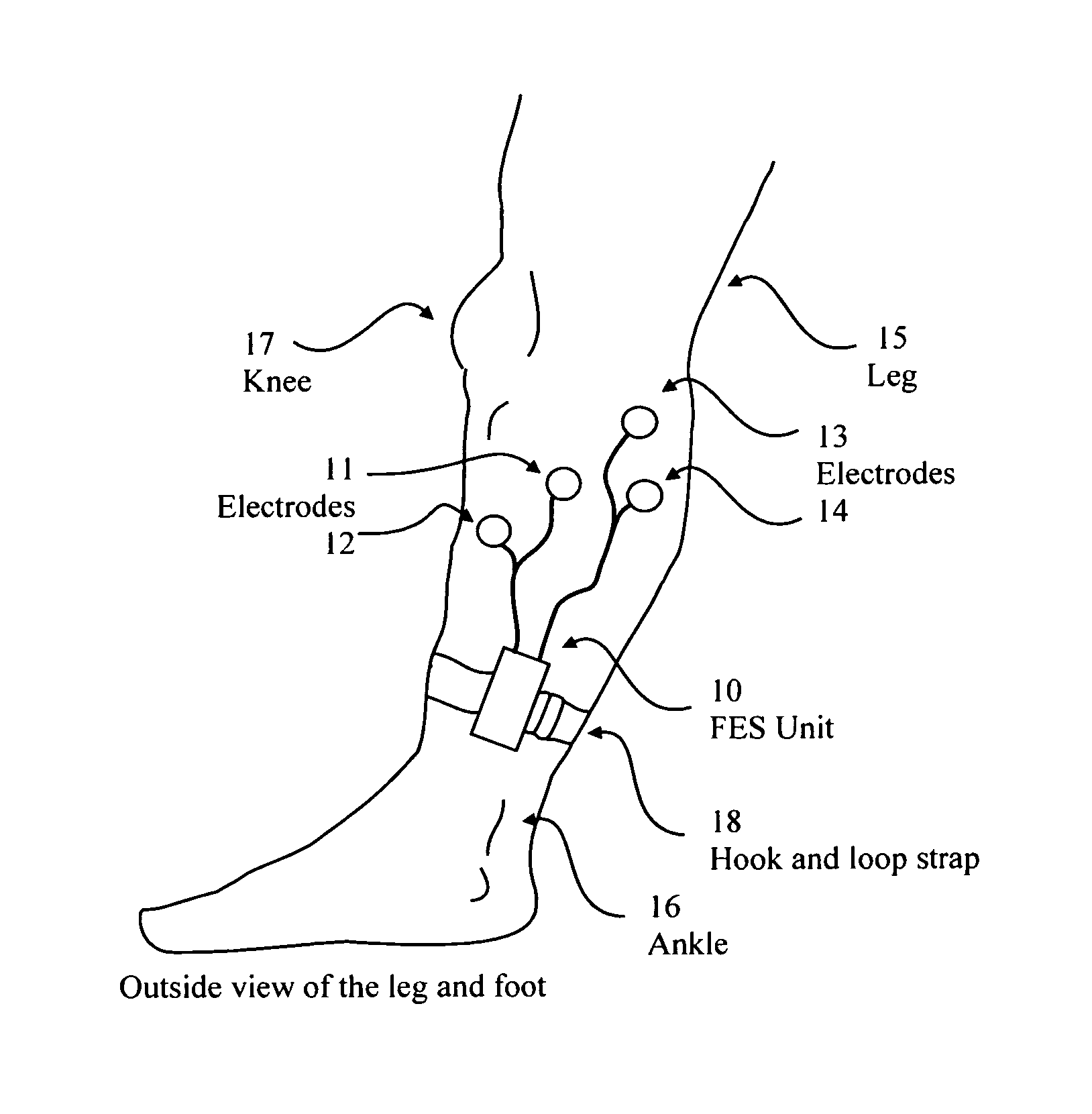
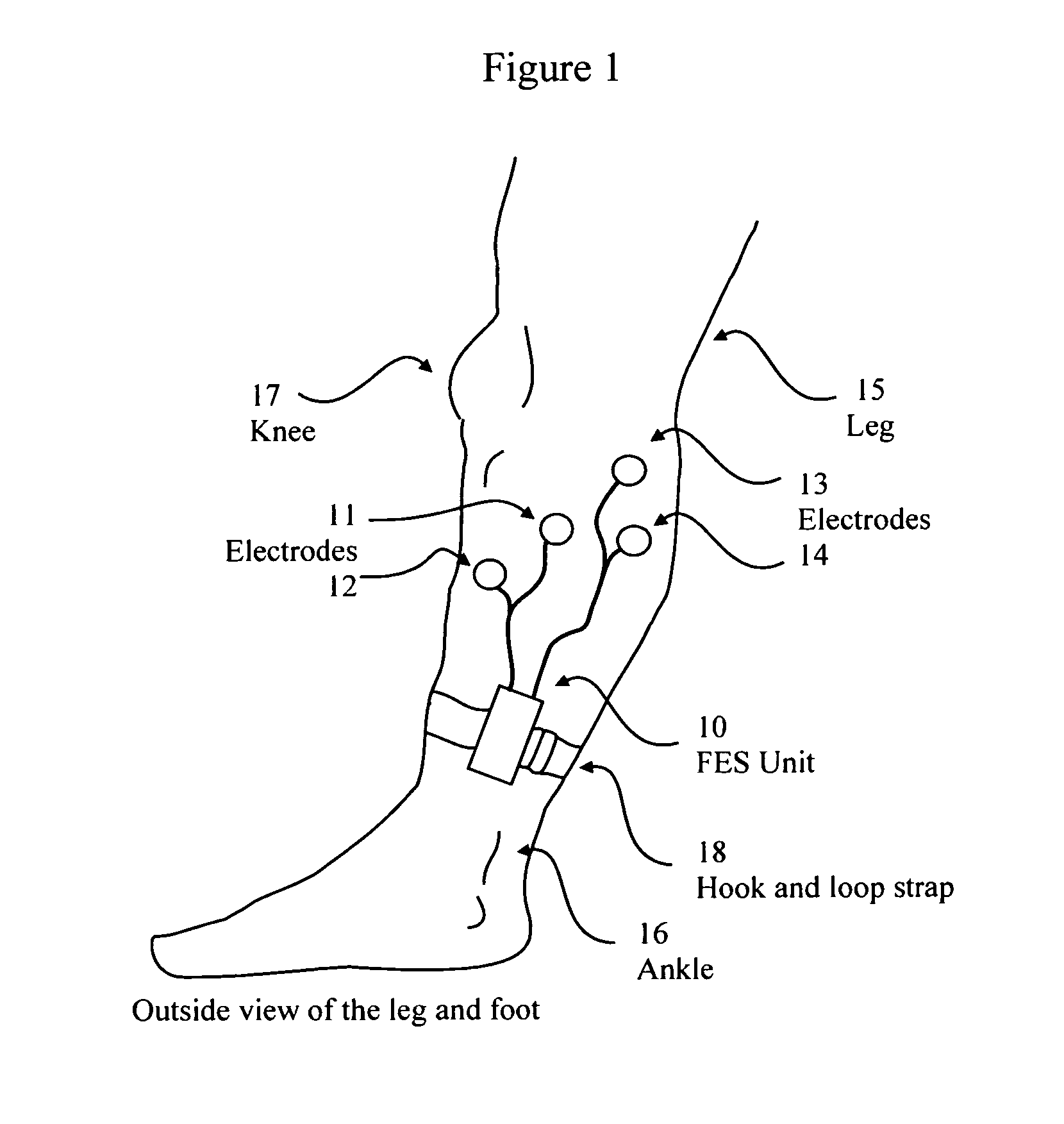
[0025]FIG. 1 shows a user wearing a preferred embodiment of the control unit of this invention on the user's leg. The control unit 10 is securely held, preferably on the outside of the user's leg 15, by a strap 18 that can be opened and closed with a hook-and-loop closure. The control unit 10 is preferably worn below the knee 17 of the user and above the ankle 16. Usually, it will be better to wear the unit just above the ankle. The reason for choosing this location is that, if the user wears long pants, the pant leg will tend to interfere with the distance sensor of the control unit 10. If the user's clothing were such that it would not interfere with the distance sensor, then the control unit could be worn on almost any place on the user's body where it could consistently be able to measure the distance from the control unit to the ground. The control unit is preferably removably attached to the body of the user under the user's clothing. Although the unit could be attached over o...


PUM


Abstract

A functional electrical stimulation method and device that starts electrical stimulation of a first leg of a person when a distance between a reference point on the person's first leg and the surface on which the person walks exceeds a first predetermined value and stops electrical stimulation of the first leg of the person when the distance between the reference point and the surface falls below a second predetermined value, wherein the first and second predetermined values are calculated from an initial measurement of the distance between the reference point and the surface when the person is standing still and the first leg is perpendicular to the surface. The first predetermined value is greater than the second predetermined value. The method and device produce a more natural gait in persons with drop foot, and minimize the time electrical stimulation is applied to muscles so as to minimize muscle fatigue.

Description

REFERENCE TO RELATED APPLICATION[0001]This application claims the benefit of 35 U.S.C. §111(b) Provisional Patent Application Ser. No. 61 / 198,294 which was filed on Nov. 4, 2008 and entitled “Functional electrical stimulus unit”.FIELD OF THE INVENTION[0002]The present invention relates to an apparatus worn by a person that has a condition known as “drop foot”. The present invention is a portable functional electrical stimulus (FES) apparatus that is intended to be worn by persons who by disease or injury or defect are unable to lift the foot while walking. The present invention electrically stimulates the nerve to cause the tibialis anterior muscle to lift the foot during the appropriate time of the swing phase of walking.BACKGROUND OF THE INVENTION[0003]Drop foot occurs when the nerve stimulation from the central nervous system has slowed or lost connection to the tibialis anterior muscle that lifts the foot during walking. This condition occurs for several reasons, some of which a...

Claims


Application Information

Patent Timeline
IPC IPC(8): A61N1/18A61N1/36
CPCA61N1/36003A61N1/18A61B5/112A61B5/1126A61B5/6828A61B5/7225A61B2562/0257A61N1/0452A61N1/36031A61N1/36034
Inventor WHITE, CARTER B.
Owner WHITE CARTER B
Learn More