Machine roomless elevator

a technology of elevators and roomless machines, which is applied in the field of elevators, can solve the problems of increasing the width of the suspension wheel and the counterweight housing, increasing the size of the hoistway, and easy interference among the hoist ropes, so as to increase the width of the suspension wheel and the height of the hoistway, and the distance between the hoistway wall and the car wall at the counterweight side can be further reduced

Inactive Publication Date: 2016-11-08
OTIS ELEVATOR CO
View PDF20 Cites 5 Cited by
  • Summary
  • Abstract
  • Description
  • Claims
  • Application Information

AI Technical Summary

Benefits of technology

[0006]The present invention is directed to a machine roomless elevator, which is reasonable in structure designs and economic in civil works, and can avoid cross interferences between the hoist ropes.
[0015]Compared with the prior art, the present invention has the following technical effects:
[0016]Firstly, in the machine roomless elevator according to the present invention, two or more counterweight suspension wheel are provided on the counterweight, and hoist ropes can be divided into a plurality of groups corresponding to the number of the counterweight suspension wheels after one ends thereof round the traction sheave, each group being fixed on a counterweight side termination after rounding corresponding one of said counterweight suspension wheels. Thus, the solution according to the present invention can solve the problem caused by too many hoist ropes, such as the increase of the widths of the counterweight suspension wheels, and the increase of the hoistway size, etc. Further, the solution according to the present invention also can avoid interferences caused by too many hoist ropes rounding one counterweight suspension wheel.
[0017]In addition, according to the present invention, a rotary plane of the traction sheave can be perpendicular to a car wall at a counterweight side, and in the projection on a hoistway transverse plane, an axis of the traction sheave and a radial line of each counterweight suspension wheel can be in parallel each other. In this situation, a rotary plane of the counterweight suspension wheel can be parallel to the car wall at a counterweight side. Thus, a distance between the hoistway wall and the car wall at a counterweight side can be further reduced. Further, interferences between the hoist ropes in the car side and the counterweight side can also be effectively avoided.

Problems solved by technology

The increase in the number of the hoist ropes can result in two troubles for a layout of the machine roomless elevator.
Firstly, it will result in the increases of widths of the counterweight suspension wheel and the counterweight housing, thereby increasing a size of the hoistway.
Secondly, interferences among the hoist ropes will be easily caused if too many hoist ropes round one counterweight suspension wheel.
However, since there are two independent and separate groups of the hoist ropes and the traction sheaves, the size of the hoistway is inevitably increased.
Further, due to limitations on the development of the traction machine, it is difficult to implement the traction machine having two traction sheaves.
However, since an axial size of the counterweight suspension wheel usually is smaller than a radial size thereof, the size of the hoistway would be increased if the rotary plane of the counterweight suspension wheel is perpendicular to the car wall at the counterweight side, which can result in the increase in costs of civil works.
Further, such arrangement of the counterweight suspension wheel also may result in interferences between the hoist ropes in the car side and the counterweight side.

Method used


Image

  • Machine roomless elevator
  • Machine roomless elevator
  • Machine roomless elevator

Examples


first embodiment

The First Embodiment

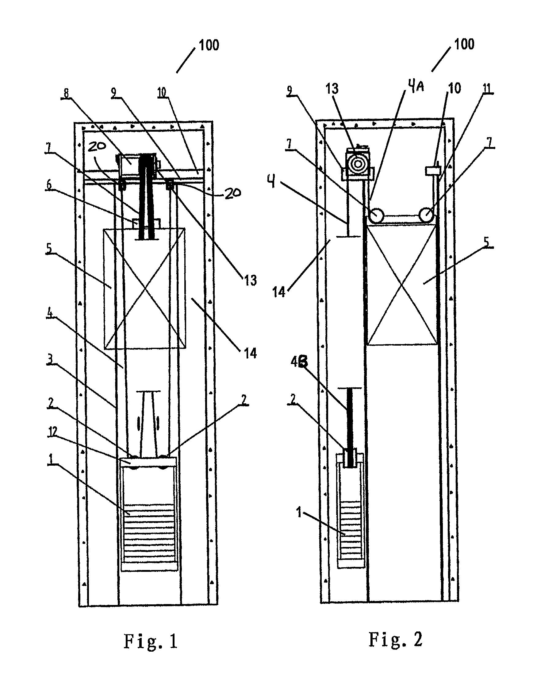
[0025]With reference to now to the figures, FIG. 1 is a plane view of a hoisway showing a machine roomless elevator according to the first embodiment of the present invention; and FIG. 2 is a left view of the hoisway of FIG. 1.

[0026]As illustrated in FIGS. 1 and 2, a machine roomless elevator 100 according to the first embodiment of the present invention comprises a counterweight 1, two counterweight suspension wheels 2, a counterweight guide rail 3, hoist ropes 4, a car 5, a car suspension wheel support member 6, two car suspension wheels 7, a traction machine 8, and a support beam 9 for supporting the traction machine 8.

[0027]The car 5 is located within an elevator hoistway 14, and has a common box-shaped structure. Typically, the car 5 can move up and down along a car guide rail 11. As shown in FIG. 2, the two car suspension wheels 7 are rotatablely disposed above the car 5 by means of the car suspension wheel support member 6. It will be understand by those s...

second embodiment

The Second Embodiment

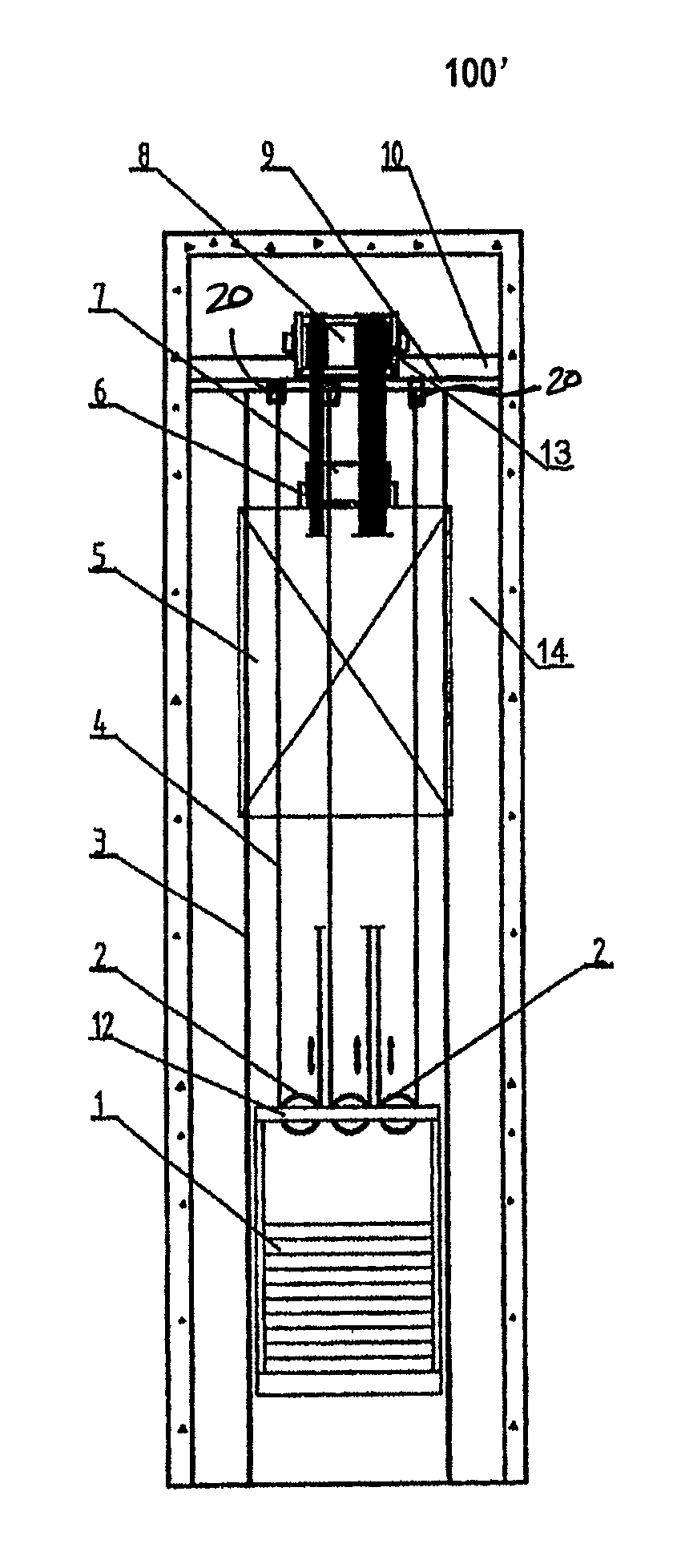
[0035]FIG. 7 is a plane view of a hoisway showing a machine roomless elevator according to the second embodiment of the present invention; and FIG. 8 is a left view of the hoisway of FIG. 7.

[0036]As illustrated in FIGS. 7 and 8. the machine roomless elevator 100′ of the second embodiment differs from that of the first embodiment in that the traction machine 8 has two traction sheaves 13, and three counterweight suspension wheels 2 are arranged on the counterweight 1. The other structures are all the same.

[0037]According to the second embodiment of the present invention, one ends 4A (e.g.. ends of the portions of the hoist ropes 4 between the car 5 and the counterweight 1, with the ends 4A being at the car side) of the hoist ropes 4 round the two car suspension wheels 7 and then are fixed on the car side rope termination 10. Further, the hoist ropes 4 can be divided into three groups after another ends 4B thereof round the traction sheave, each group being fixed ...


PUM


Abstract

A machine roomless elevator comprises a car (5) within a hoistway (14), a counterweight (1) within a space between said car (5) and a wall of said hoistway (14) and on which a plurality of counterweight suspension wheels (2) are arranged, and a traction sheave (13). Hoist ropes (4) can be devided into a plurality of groups corresponding to the number of said counterweight suspension wheels (2) after one ends thereof round said traction sheave (13), each group being fixed on a counterweight side termination after rounding corresponding one of said counterweight suspension wheels (2).

Description

FIELD OF INVENTION[0001]The present invention relates generally to an elevator, and more specifically to a machine roomless elevator.BACKGROUND OF THE INVENTION[0002]Currently, a machine roomless elevator has been increasingly used in various occasions since it occupies smaller spaces than conventional elevators having a machine room. The machine roomless elevator usually includes a long strip-shaped traction machine which has a traction sheave with a smaller diameter. The long strip-shaped traction machine refers to a machine having a smaller radial size and a larger axial size which usually occupies smaller hoistway spaces. Thus, such traction machine can have a smaller overall size, and can be easily installed on a hoistway. Further, such traction machine and a fixing base thereof have a good stress status.[0003]However, in order to satisfy a standard requirement that a diameter of the traction sheave should be 40 times or more than those of hoist ropes, the smaller diameter of t...

Claims


Application Information

Patent Timeline
Patent Type & Authority Patents(United States)
IPC IPC(8): B66B11/08B66B7/06B66B11/00
CPCB66B11/08B66B11/008B66B7/06
Inventor LIN, TIANMINGZHANG, JIANWEIHE, FEIQUNZHANG, GUOHUA
Owner OTIS ELEVATOR CO
Why Eureka
Try Eureka