
Spectral imaging system and method

a spectral imaging and detection system technology, applied in the field of spectral xray detection and imaging, can solve the problems of imperfect energy response of currently achievable photon counting detectors, depth information that cannot be retained by multi-layer pcxd techniques or proposed to improve spectral imaging, and the depth information is not expected to have any benefit, so as to improve the overall energy response, increase the counting rate of detectors, and improve the effect of overall energy respons

Inactive Publication Date: 2016-11-08
THE BOARD OF TRUSTEES OF THE LELAND STANFORD JUNIOR UNIV
View PDF4 Cites 17 Cited by
  • Summary
  • Abstract
  • Description
  • Claims
  • Application Information

AI Technical Summary

Benefits of technology

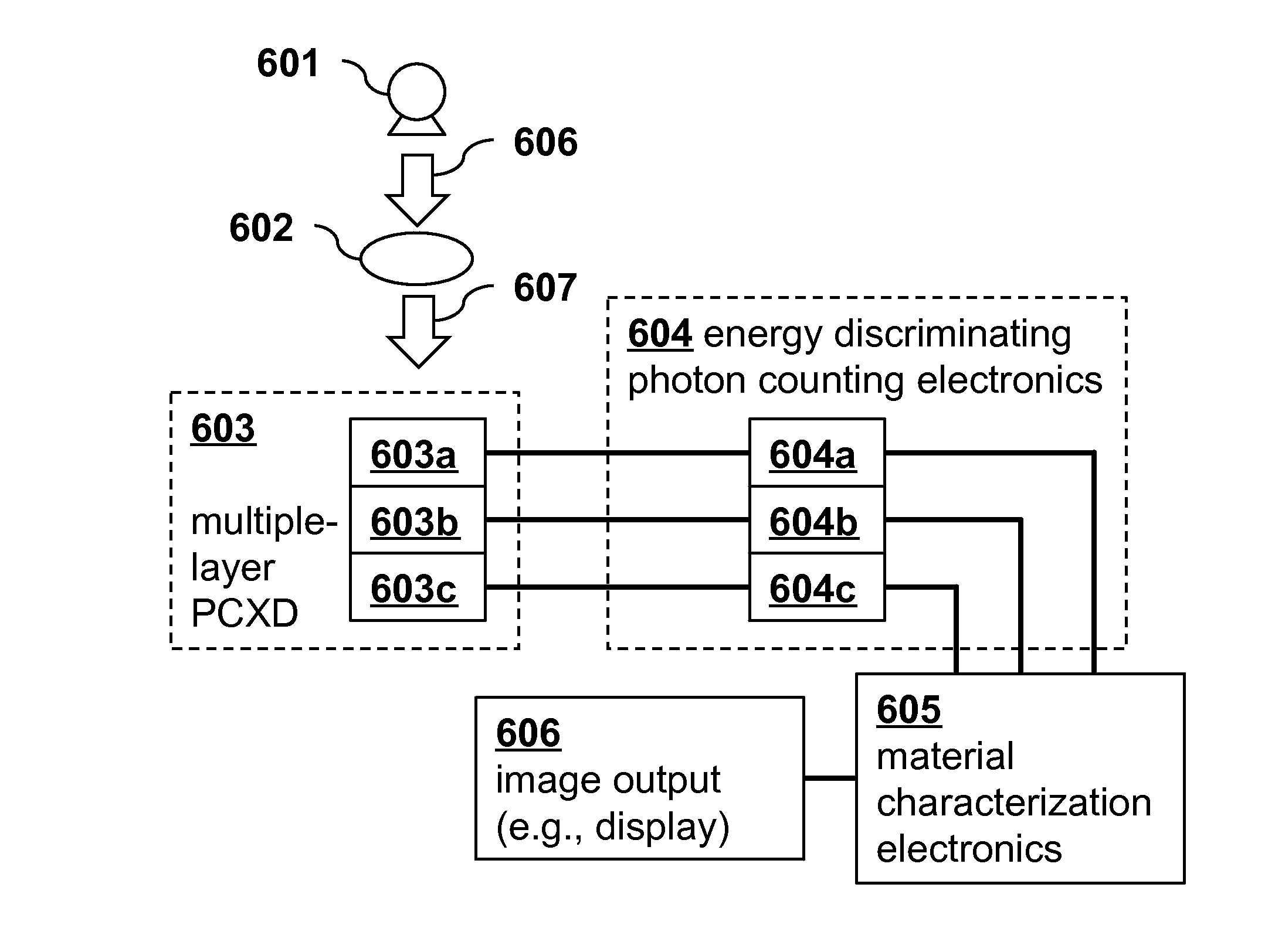
The present invention provides a method to improve the energy response of photon counting detectors by using depth segmentation and retaining the depth dependence of spectral data. This results in improved material-specific or spectral information from x-ray measurements. The simultaneous use of energy information from photon counting and from depth response provides surprising advantageous improvements for spectral x-ray imaging and material characterization.

Problems solved by technology

In addition, assuming an ideal energy response of the PCXD, retaining depth-specific data from the PCXDs provides no additional information, and such depth information would not be expected to have any benefit.
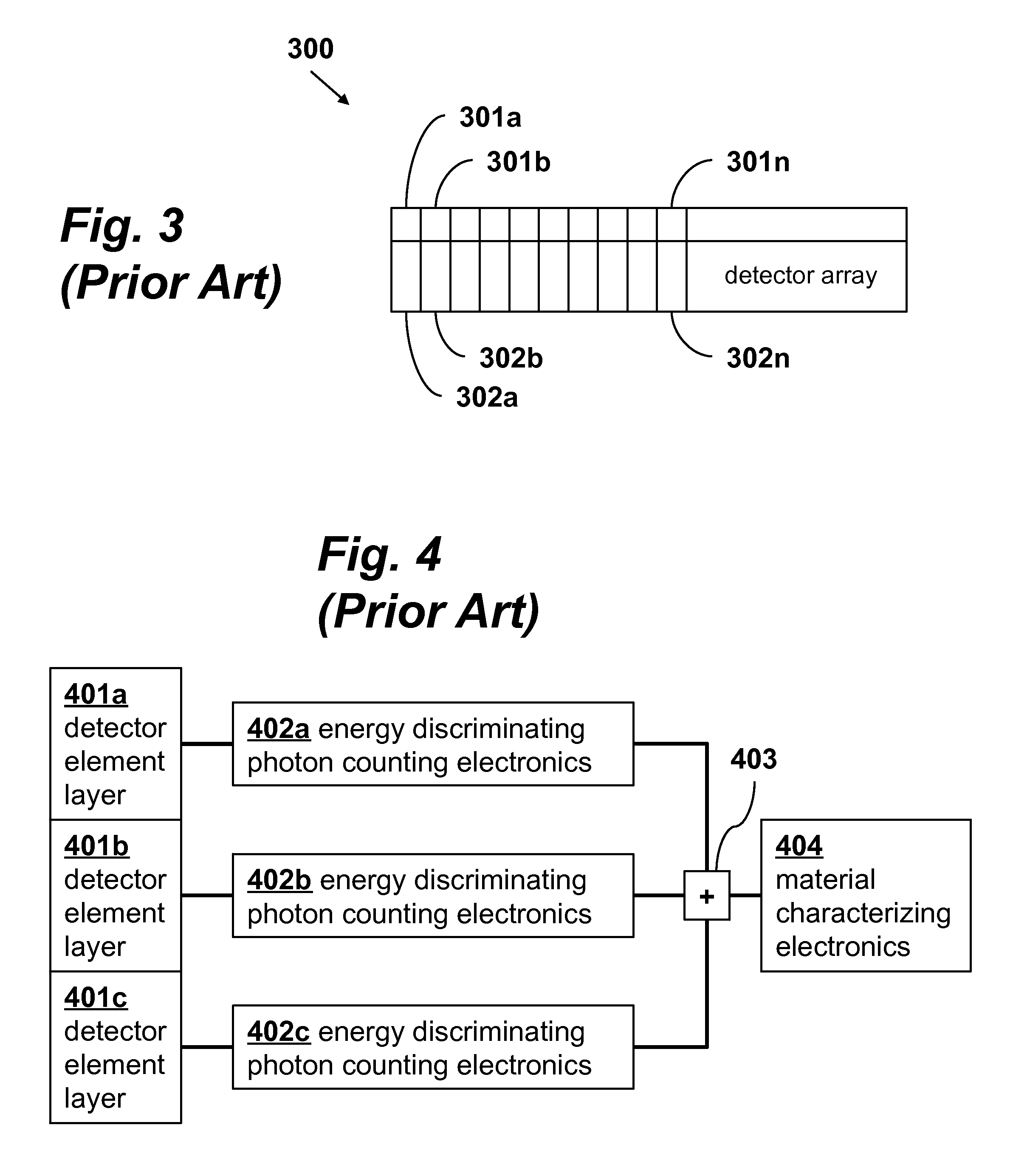
Consequently, none of the known multi-layer PCXD techniques retain the depth information from the separate layers or propose to use it to improve spectral imaging.
However, the energy response of currently achievable photon counting detectors is imperfect.
However, many photons scatter in the detector and deposit only a fraction of their energy.
With the prior art methods these events are not very useful for energy analysis.

Method used


Image

  • Spectral imaging system and method
  • Spectral imaging system and method
  • Spectral imaging system and method

Examples


Embodiment Construction

[0026]The significance of the present invention can be appreciated by first considering the design of known devices and techniques for spectral x-ray imaging.

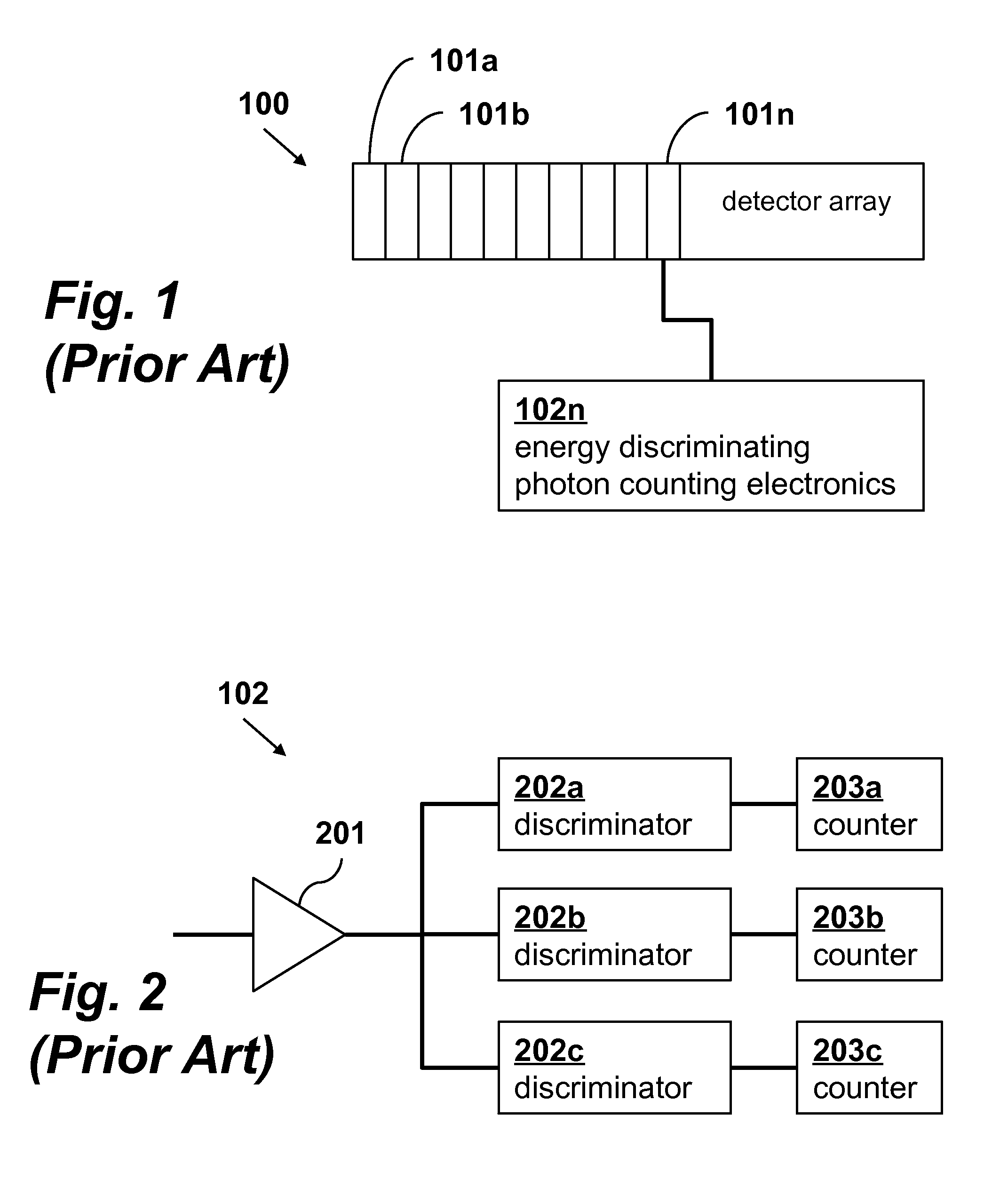
[0027]FIG. 1 shows a conventional photon counting detector array 100. While spectral imaging can be accomplished using only a single detector element, generally, especially for CT systems, a plurality of spatially distributed detector elements 101a, 101b, . . . 101n, etc. are included in detector array 100. Each element of the photon counting energy discriminating detector 100 is connected to energy discriminating photon counting electronics. Shown in FIG. 1 is detector element 101n connected to electronics 102n that process the detector signals from that element. Although not shown, each element is similarly connected to its own signal processing electronics.

[0028]The electronics of a representative processing channel, such as 102n of FIG. 1, are shown in more detail in FIG. 2 and named 102 in that figure. The signal from each...


PUM

PropertyMeasurementUnit
energyaaaaaaaaaa
photon energyaaaaaaaaaa
photon counting x-ray detectoraaaaaaaaaa

Abstract

Spectral x-ray imaging using a photon counting x-ray detector (PCXD) transmits a broad spectrum x-ray beam through an object, detects the transmitted x-ray beam with the PCXD and processes the detected signals to determine material characteristics of the object using both the detected signals as a function of detector layer and the detected signals as a function of the particular energy band. Each detector layer of the multiple detector layers produces at least two signals, each signal representing a detected x-ray intensity in a particular energy band, and the depth information contained in the separate read-out channels.

Description

CROSS-REFERENCE TO RELATED APPLICATIONS[0001]This application claims priority from U.S. Provisional Patent Application 61 / 917,929 filed Dec. 18, 2013, which is incorporated herein by reference.FIELD OF THE INVENTION[0002]This invention relates generally to spectral x-ray detection and imaging. More specifically, it relates to improved systems and methods for determining material characteristics from x-ray measurements using photon counting detectors.BACKGROUND OF THE INVENTION[0003]Traditional x-ray imaging techniques employ integrating detectors that detect the total intensity of a transmitted beam through an object to be imaged. Because different materials (such as bone and tissue) attenuate the x-ray beam by different amounts, the resulting detected intensity will vary accordingly. In order to improve the ability to discriminate between materials, spectral x-ray imaging techniques have been developed. These techniques allow for enhanced discrimination between different materials ...

Claims


Application Information

Patent Timeline
Patent Type & Authority Patents(United States)
IPC IPC(8): G01N23/00G01T1/24G01N23/04A61B6/00A61B6/03
CPCG01T1/247A61B6/4241G01N23/046A61B6/032A61B6/482A61B6/483A61B6/5217
Inventor PELC, NORBERT J.
Owner THE BOARD OF TRUSTEES OF THE LELAND STANFORD JUNIOR UNIV
Learn More