Multi-mode composite antenna

Inactive Publication Date: 2016-11-08
STELLENBOSCH UNIVERSITY
View PDF7 Cites 7 Cited by
  • Summary
  • Abstract
  • Description
  • Claims
  • Application Information

AI Technical Summary

Benefits of technology

The invention is about a radio telescope that can control the direction in which it scans for signals without needing to move the equipment. It uses an antenna array to create a wide field of view, and uses electronics to shape the coverage area to improve accuracy. This allows for more efficient and precise detection of signals.

Problems solved by technology

However, the radiation pattern of an antenna element is never completely omni-directional, as there is always a direction from which an antenna receives less power than its optimal direction.
However, the combination of a single monopole and dipole do not produce a radiation pattern that is very hemispherical as there are multiple local minima.
In addition, collocation of the monopole and dipole is generally a problem and many previous attempts to combine monopoles and dipoles are sub-optimal because they are not accurately collocated.
Although this disclosure addresses the collocation problem, the described antenna requires a common-mode rejection filter and the resultant complexities which that entails.
The non-shielded transmission line may also result in spurious interference even when driven by differential mode excitation.

Method used


Image

  • Multi-mode composite antenna
  • Multi-mode composite antenna
  • Multi-mode composite antenna

Examples


first embodiment

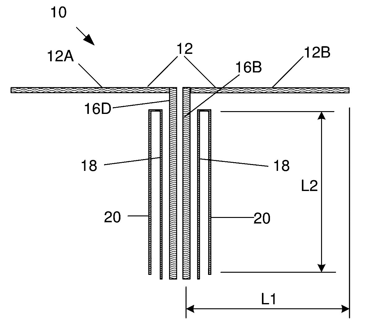
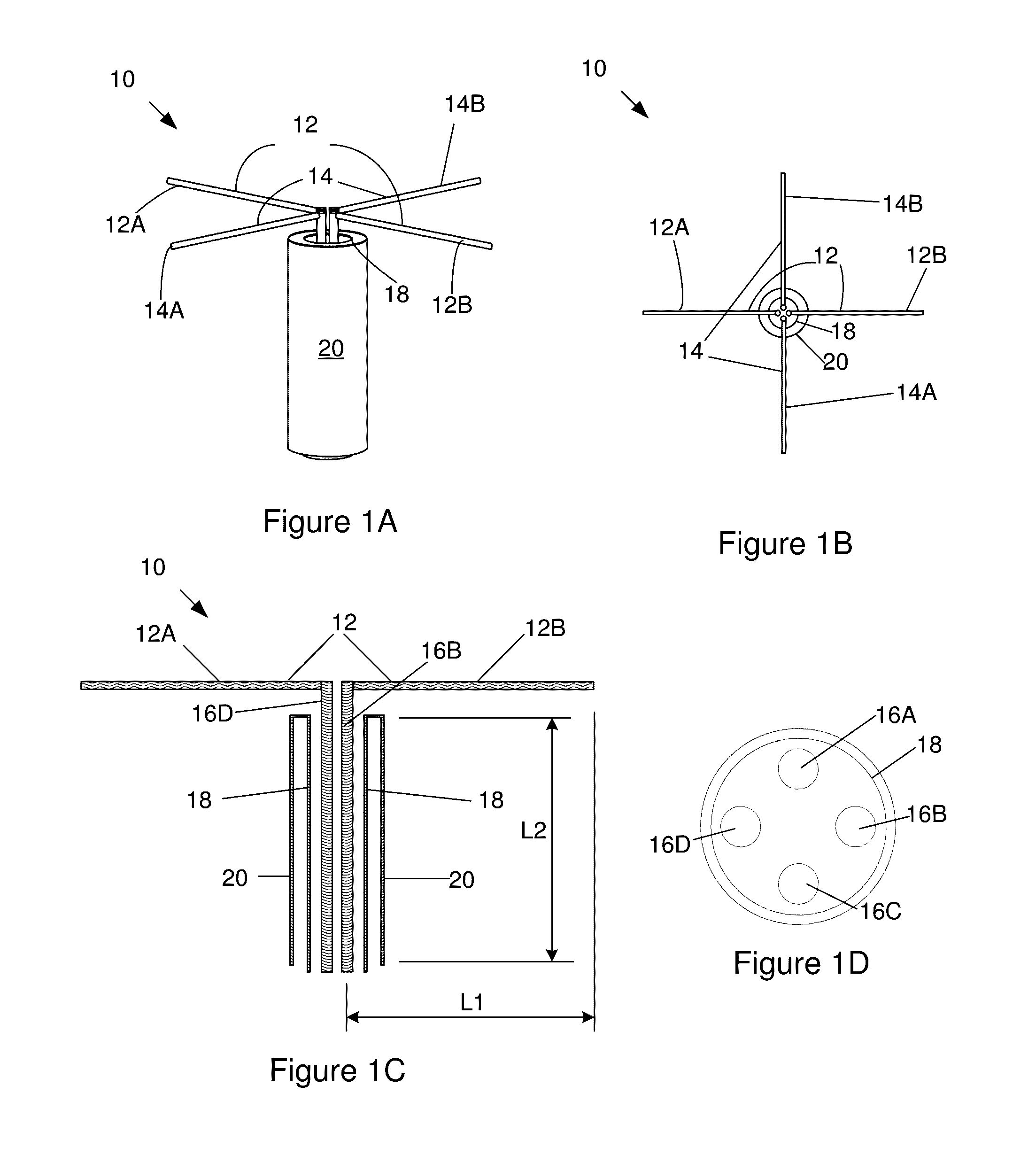
[0047]FIGS. 1A to 1C illustrate a multi-mode composite antenna (10) according to the invention. The antenna (10) includes first and second dipole elements (12, 14) which each have a pair of collinear arms (12A, 12B, 14A, 14B) extending in opposed directions along a common plane. In this embodiment the arms are cylindrical conductive elements and the arms (12A, 12B) of the first dipole element (12) extend perpendicularly to the arms (14A, 14B) of the second dipole element (14).

[0048]Each of the dipole arms is connected to a separate signal transmission line (16A, 16B, 16C, 16D), shown most clearly in FIG. 1D. The four signal transmission lines extend within a conductive right cylindrical tube (18) which forms a shield for the signal transmission lines. The cylindrical tube (18) has an extension which has been folded back over itself to form an outer sleeve (20) that extends in parallel with the conductive tube (18), as most clearly seen in FIG. 1C. The conductive tube (18) is connect...

second embodiment

[0067]FIGS. 10A to 10C show a multi-mode composite antenna (100) according to the invention, which has improved operating bandwidth as compared to the antenna (10) of FIGS. 1A to 10. The composite antenna (100) includes first and second dipole elements (102, 104), which each have a pair of collinear arms (102A, 102B, 104A, 104B) extending in opposed directions along a common plane. In this embodiment each arm is made from sheet material which widens towards free ends thereof to form generally sector-shaped dipole arms. The sector-shaped dipole arms can be made as solid metal plates or, in the illustrated embodiment, can be printed on a substrate (105). The arms (102A, 102B) of the first dipole element (102) extend perpendicularly to the arms (104A, 104B) of the second dipole element (104). As shown in FIG. 10C, the length (L1) of each arm of each dipole element (102) is equal to the height (L2) of the extension of the conductive tube which forms the monopole element, as measured per...


PUM


Abstract

A multi-mode composite antenna is disclosed. The antenna includes at least two dipole elements, each dipole element having two arms with a signal transmission line connected to each arm, a conductive tube in which the signal transmission lines extend which forms a shield for the signal transmission lines, and an extension of the conductive tube. In one embodiment, the extension is formed by the conductive tube being folded back over itself. The dipole elements are capable of being excited by at least one differential mode excitation to realize a dipole radiation pattern, and the extension forms a monopole element with a monopole radiation pattern when at least one dipole element is excited by a common mode excitation. The composite antenna is capable of a combined monopole and dipole radiation pattern through the application of both differential mode excitation and common mode excitation.

Description

CROSS-REFERENCE(S) TO RELATED APPLICATIONS[0001]This application is the U.S. national stage application of International Application PCT / IB2015 / 050300, filed Jan. 15, 2015, which international application was published on Jul. 23, 2015, as International Publication WO 2015 / 107473 in the English language. The International Application claims priority of South African Provisional Patent Application 2014 / 00363, filed Jan. 17, 2014.FIELD OF THE INVENTION[0002]This invention relates to an antenna and, more specifically, to a multi-mode composite antenna.BACKGROUND TO THE INVENTION[0003]In many wireless antenna applications it is desirable to receive or transmit signals from a wide variety of possible angles. However, the radiation pattern of an antenna element is never completely omni-directional, as there is always a direction from which an antenna receives less power than its optimal direction. For straight wire antennas, such as monopole or dipole antennas, the radiation pattern is ze...

Claims


Application Information

Patent Timeline
IPC IPC(8): H01Q25/04H01Q9/28H01Q9/40H01Q21/26H01Q9/26H01Q9/16
CPCH01Q9/16H01Q9/28H01Q9/40H01Q21/26H01Q9/30H01Q21/29
Inventor PRINSLOO, DAVID SCHALK VAN DER MERWEMEYER, PETRIEMAASKANT, ROBIVASHINA, MARIANNA VALERIEVNA
Owner STELLENBOSCH UNIVERSITY
Why Eureka
Try Eureka