Compact illumination system

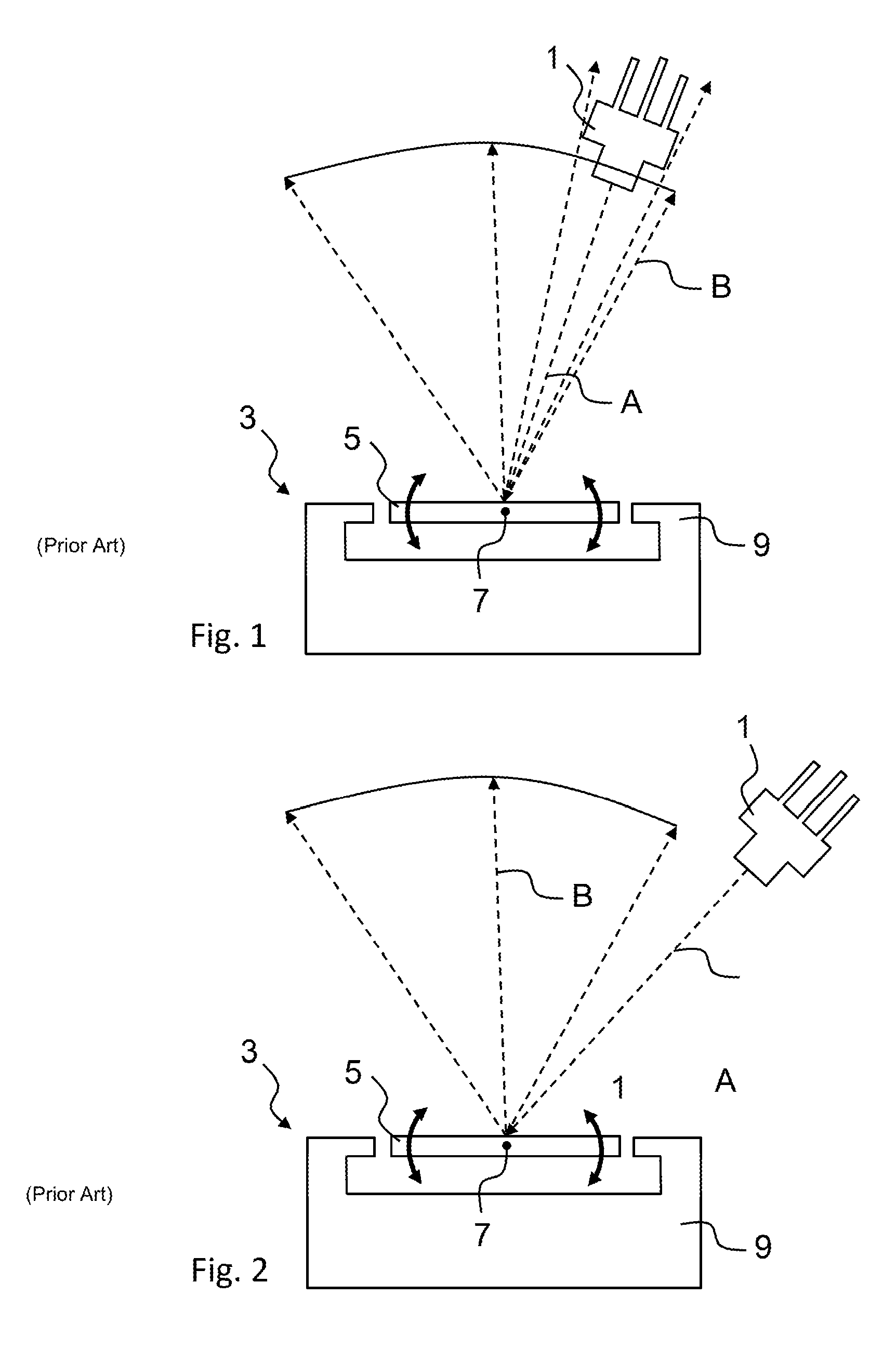
a compact, light-emitting technology, applied in the direction of lighting and heating apparatus, instruments, lenses, etc., can solve the problems of obstructing some of the reflection light, occluded or non-illuminated spots behind the light source, and the arrangement of fig. 1 is also not optimal in terms of space use, so as to achieve high production volume, low cost, and high yield of manufacturing process

Active Publication Date: 2016-11-29
GOOGLE LLC
View PDF14 Cites 5 Cited by
  • Summary
  • Abstract
  • Description
  • Claims
  • Application Information

AI Technical Summary

Benefits of technology

[0010]The proposed solution provides a more compact illumination system since the light source is located in front of the scanning mirror assembly and thus the length of the light path from the light source to the reflective surface and onwards to an output aperture of the system can be minimised. The shadow or occlusion effect caused by the obstruction of the reflected light by the light source are mitigated by means of the optical element, which is placed so that it directs the reflected light into the occlusion region. Thus, the present invention at least partially overcomes the known problem that if the light is reflected back towards the light source, the light source occludes the reflected light.
[0030]The proposed manufacturing process provides the advantage that it is suitable for very high volume production at low cost. Another advantage of the manufacturing process is that the obtainable manufacturing process yield is high. This is for example due to very small number of optical components per illumination system. In its simplest form, only three optical components, namely the light source, the optical element and the reflective surface, are needed. Also, the intended orthogonal arrangement of the light source with the mirror reflective surface may be out of alignment, and the system would still perform well. Another advantage is that number of reflections in the light path is minimised, thereby also minimising light loss, because each reflection introduces some light loss and then generates some “parasitic light” which may impair the resulting illumination profile.

Problems solved by technology

However, in this position the light source would obstruct the reflected light, thereby creating an occluded or non-illuminated spot behind the light source.
However, the light source still obstructs some of the reflected light in the position as shown in FIG. 1.
Furthermore, the arrangement of FIG. 1 is also not optimal in terms of use of space.
Now the light source no longer obstructs the reflected signals, but the configuration has the disadvantage that it takes up even more space than the configuration of FIG. 1, and the resulting or reflected image becomes clearly deformed due to the large angle of incidence of the light A striking the surface of the mirror.
It is also to be noted that the current manufacturing processes of the above type illumination systems are not optimal.
This naturally increases the complexity of the manufacturing process.

Method used


Image

  • Compact illumination system
  • Compact illumination system
  • Compact illumination system

Examples


Embodiment Construction

[0044]An embodiment of the present invention will now be described in detail with reference to the attached figures. Identical or corresponding functional and structural elements which appear in the different drawings are assigned the same reference numerals.

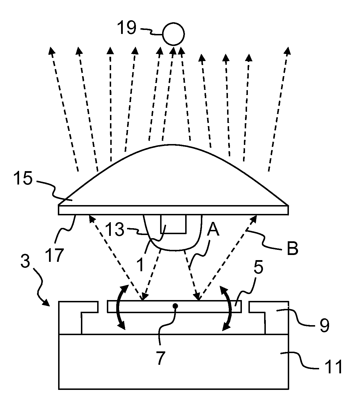
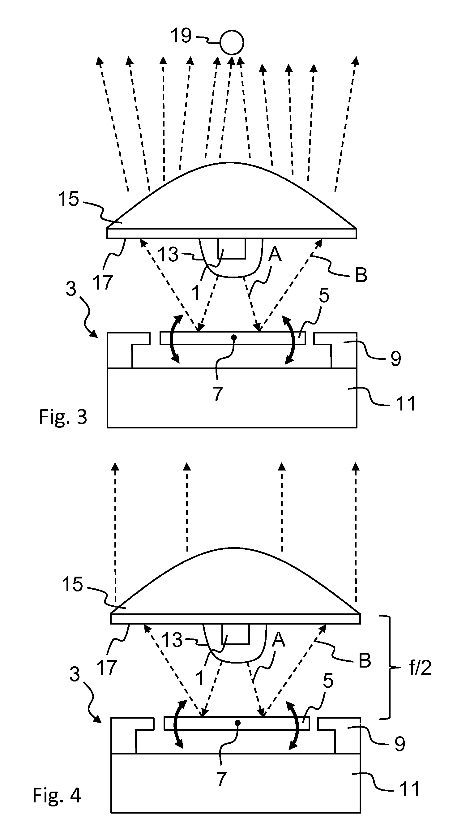
[0045]FIG. 3 is a schematic cross-sectional view illustrating an exemplary illumination or lighting system or device according to an embodiment of the present invention. This arrangement may be used for example in photographic flash applications or in 3D sensing solutions used for example in gesture sensing applications and / or three dimensional mapping of an object or the environment. FIG. 1 shows a light source 1. Various types of light sources and packaging may be used; light source 1 may be for example an edge emitting laser diode, a vertical-cavity surface-emitting laser (VCSEL), a light emitting diode (LED), a resonant-cavity LED, a micro-LED or an array of such light sources. The light source may be a monochromatic laser l...


PUM


Abstract

An illumination system includes a light source arranged for emitting non-collimated light towards a reflective surface of a scanning mirror assembly such that the light source occludes a region of the light reflected from the reflective surface. The scanning mirror assembly includes the reflective surface, which is arranged to be rotationally displaced around at least one rotation axis. The illumination system also includes an optical element for changing the propagation direction of the said reflected light so as to illuminate at least a part of the said occluded region.

Description

TECHNICAL FIELD[0001]The invention relates to the field of illumination systems to be used for instance in photographic flash or 3D sensing applications. More specifically, the present invention relates to illumination systems comprising at least one scanning mirror assembly. The invention also relates to a corresponding method of fabricating the illumination system.BACKGROUND OF THE INVENTION[0002]Scanning mirror-based light projection systems are known in the field of illumination systems. US2014 / 0029282 discloses an example of such a system, in which the light source is a laser type light source. A scanning mirror rotatable around two orthogonal axes is actuated and receives a light signal from a primary light source to project an image on to a phosphorous element. The light radiated by the primary light source, or more specifically its luminous intensity, for example, can be modulated to project a desired image on to the phosphorous element. The phosphorous element is then arran...

Claims


Application Information

Patent Timeline
Patent Type & Authority Patents(United States)
IPC IPC(8): G02B26/10G02B19/00G02B3/00F21V9/40
CPCG02B26/105G02B19/0028G02B19/0061F21V5/04F21V14/04G02B26/0833G02B19/0085H01L25/167H01L33/58H01L33/60
Inventor ABELE, NICOLASKILCHER, LUCIO
Owner GOOGLE LLC
Why Eureka
Try Eureka