
Touch panel with pressing-force measuring performance

a technology of pressing force and touch panel, applied in the field of touch panel, can solve the problems of touch panel thickness increase, undesirable change in optical properties, touch panel, etc., and achieve the effect of maintaining optical properties and reducing manufacturing costs

Inactive Publication Date: 2016-11-29
NISSHA PRINTING COMPANY
View PDF6 Cites 26 Cited by
  • Summary
  • Abstract
  • Description
  • Claims
  • Application Information

AI Technical Summary

Benefits of technology

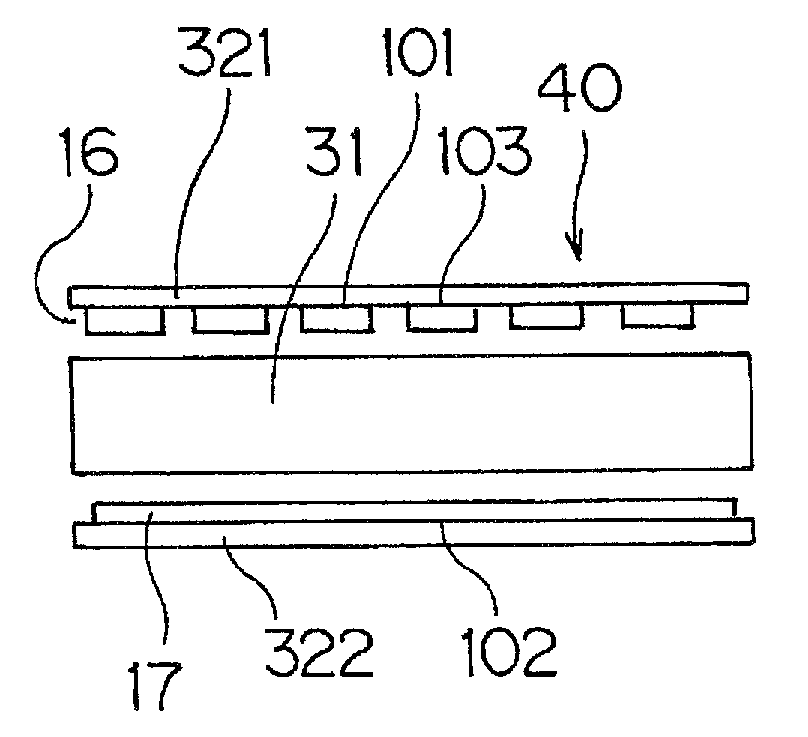
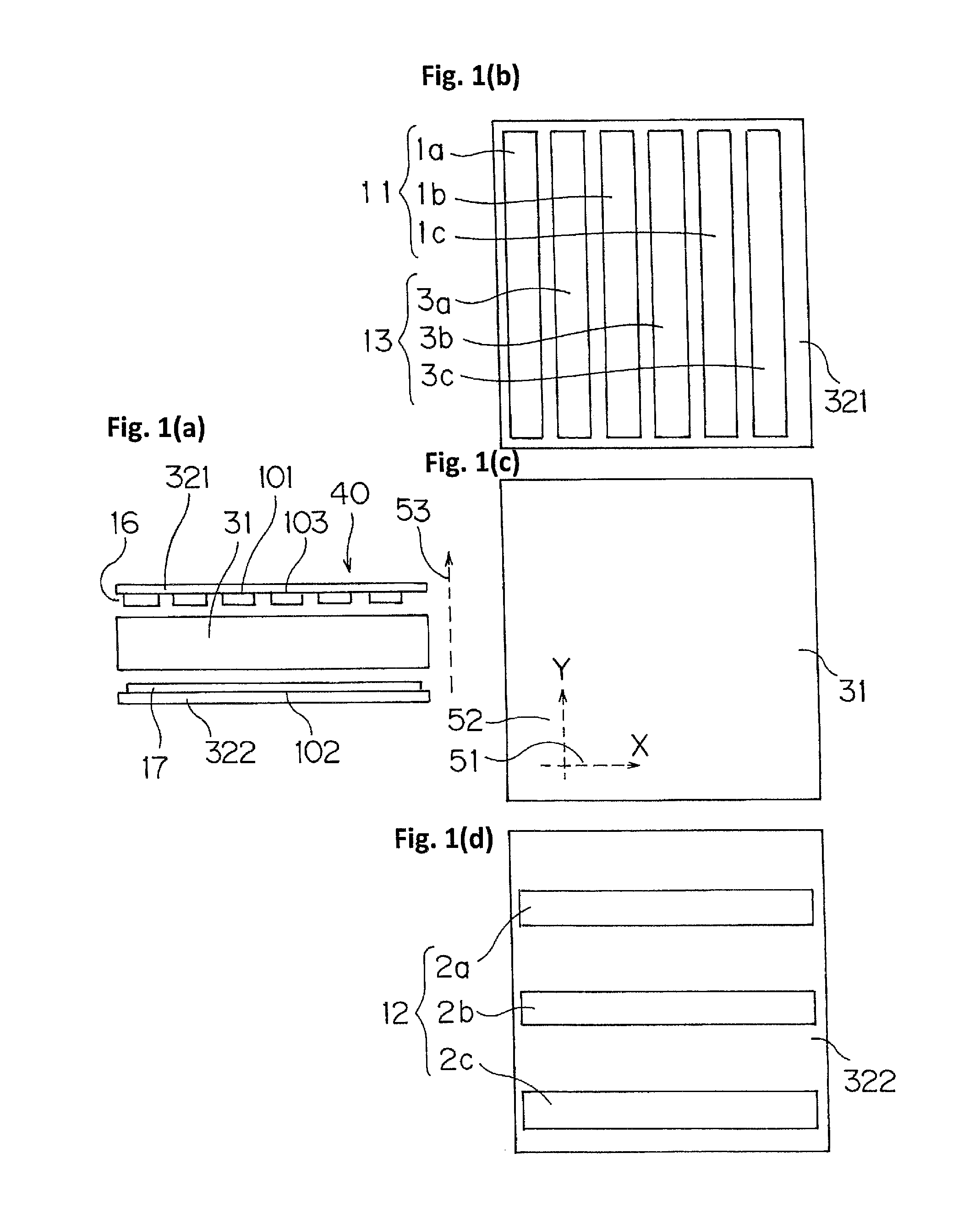
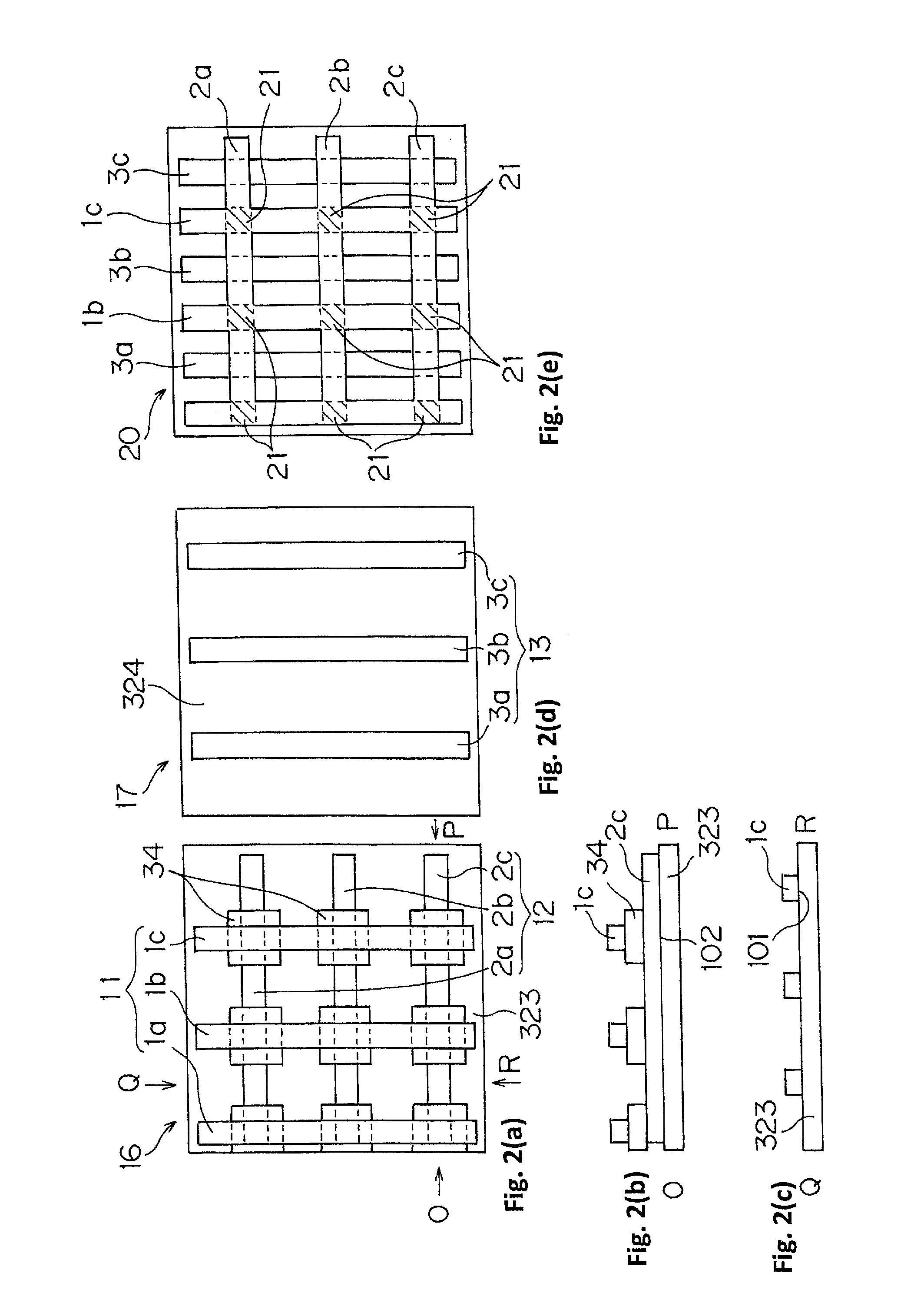
The present invention provides a touch panel that can measure force and detect points of contact. It includes an upper electrode and a lower electrode, which are both partially form a plane and are placed on the sides of the piezoelectric body. This design allows for the fabrication of thin touch panels with good optical properties and reduces manufacturing costs.

Problems solved by technology

Such layer of the two types of sensors result in increased thickness of touch panels, undesirable change in optical properties, such as transparency, of touch panels, and increased manufacturing cost.

Method used


Image

  • Touch panel with pressing-force measuring performance
  • Touch panel with pressing-force measuring performance
  • Touch panel with pressing-force measuring performance

Examples


Embodiment Construction

[0079]The touch panel and electronic device according to the embodiments of the present invention are further described below referring to the figures. Some of the figures referred herein are pattern diagrams containing magnification of some elements for easy understanding of the present invention. Thus some of the dimensions or dimensional ratio between the elements may be different from that of actual devices. The dimensions, materials, forms, and relative positions of the members and parts described in the working examples of the present invention merely describe the present invention and are not intended to restrict the scope of the present invention unless otherwise specified. The numbers used as the signs may collectively represent parts, and alphabetical letters are sometimes added to such numbers for representing each of such parts. For example, the first conductive members are represented by the sign, 1, and each first conductive member is represented by the sign, 1a, 1b or...


PUM


Abstract

A touch panel equipped with both a capacitive sensor and a piezoelectric sensor, wherein the touch panel solves the problems of increased panel thickness, changes in the optical properties, and increased manufacturing costs. This touch panel is provided with force measurement using a piezoelectric body and capacitive point detection. The force measurement uses a pair of electrodes arranged with the piezoelectric body sandwiched therebetween. The point detection uses one electrode and another electrode. At least one top electrode is disposed on the side of the top surface of the piezoelectric body, and at least one bottom electrode is disposed on the side of the bottom surface of the piezoelectric body. One electrode among the pair of electrodes used in force measurement is a bottom electrode, and at least one electrode among the two electrodes used in point detection is a top electrode.

Description

RELATED APPLICATIONS[0001]The present application is National Phase of International Application No. PCT / JP2013 / 084583 filed Dec. 25, 2013, and claims priority from Japanese Applications No. 2013-033974, filed Feb. 23, 2013 and No. 2013-110656 filed May 27, 2014, the disclosure of which is hereby incorporated by reference herein in its entirety.TECHNICAL FIELD[0002]The present invention relates to a touch panel provided with performances of pressing force measurement using a piezoelectric body and point detection by capacitive sensing system.BACKGROUND ART[0003]A touch panel has a capacitive sensor to detect an input point and a piezoelectric sensor to measure pressing force.[0004]Touch panels functioning as both capacitive and piezoelectric sensors to detect an input point and measure pressing force have been known in prior art (for example, those disclosed in Patent literatures 1 and 2). These conventional touch panels are fabricated by layering a capacitive sensor on the top or b...

Claims


Application Information

Patent Timeline
Patent Type & Authority Patents(United States)
IPC IPC(8): G06F3/045G06F3/044G06F3/041
CPCG06F3/0414G06F3/044G06F2203/04105G06F2203/04106G06F3/0445G06F3/0446
Inventor WATAZU, YUJISHIBATA, JUNICHIOKUMURA, SHUZOOZAKI, KEISUKEHASHIMOTO, TAKAO
Owner NISSHA PRINTING COMPANY
Learn More