Motor

a technology for motors and components, applied in the field of motors, can solve the problems of increasing the possibility of lead wire disconnection, and achieve the effects of preventing lead wire disconnection, preventing deformation, and maintaining bonding strength

Active Publication Date: 2016-11-29
NIDEC CORP
View PDF12 Cites 9 Cited by
  • Summary
  • Abstract
  • Description
  • Claims
  • Application Information

AI Technical Summary

Benefits of technology

[0008]In accordance with an aspect of a preferred embodiment of the present invention, a motor includes a stator around which an armature coil is wound; a bus bar unit including a coil-connection bus bar electrically connected to the armature coil and an electronic-component-connection bus bar to which a plurality of electronic components is welded; and a bus bar holding member arranged to hold the bus bar unit, wherein the electronic-component-connection bus bar includes an electronic component welding portion including a plurality of welding points at which the electronic components are welded to a leading end of the electronic component welding portion, a base portion held by the bus bar holding member, and a connection portion configured to interconnect the electronic component welding portion and the base portion, a distance between the welding points adjoining each other being larger than a width of a thinnest section of the connection portion. With a structure in which an electronic-component-connection bus bar is configured to be readily deformed in different directions, it is possible to maintain a bonding strength and to prevent disconnection of lead wires.

Problems solved by technology

This further increases the possibility of disconnection of lead wires.

Method used


Image

  • Motor
  • Motor
  • Motor

Examples


Embodiment Construction

[0016]Preferred embodiments of motors according to the present invention will now be described with reference to the accompanying drawings. The drawings are not shown on a particular reduction scale. The preferred embodiments and the drawings described below are presented merely for the sake of convenience in description. The scope of the present invention is not limited to the preferred embodiments described below. Technical features of the preferred embodiments may be combined depending on the necessity.

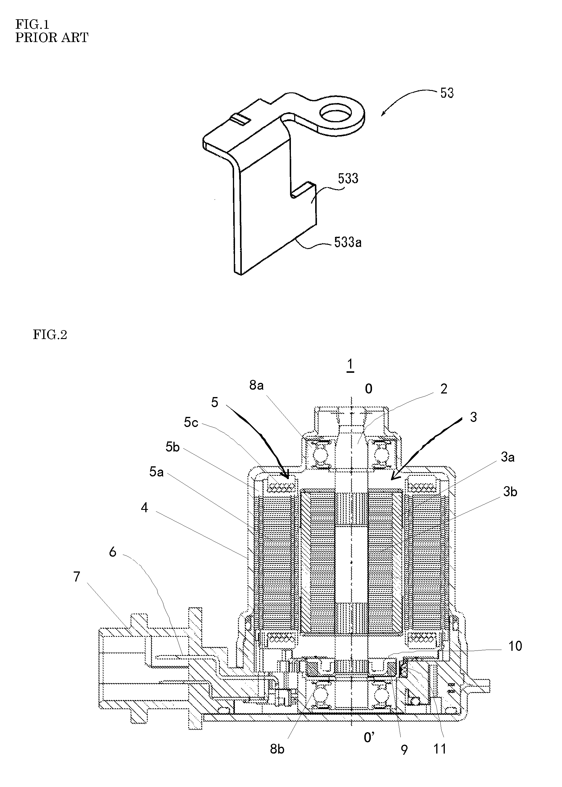
[0017]In the following description, the term “axial direction” indicates the direction of a center axis 0-0′ of a motor. The term “radial direction” indicates the direction of a radius extending from the center axis 0-0′. The term “upper” indicates the side at which a rotor is positioned in the axial direction. The term “lower” indicates the side at which a bus bar holding member is positioned in the axial direction.

[0018]FIG. 2 is a sectional view showing a motor according to a pr...


PUM


Abstract

A motor includes a stator around which an armature coil is wound, a bus bar unit including a coil-connection bus bar electrically connected to the armature coil and an electronic-component-connection bus bar to which a plurality of electronic components is welded, and a bus bar holding member arranged to hold the bus bar unit. The electronic-component-connection bus bar includes an electronic component welding portion including a plurality of welding points at which the electronic components are welded to a leading end of the electronic component welding portion, a base portion held by the bus bar holding member, and a connection portion configured to interconnect the electronic component welding portion and the base portion. A distance between the welding points adjoining each other is larger than a width of a thinnest section of the connection portion.

Description

BACKGROUND OF THE INVENTION[0001]1. Field of the Invention[0002]The present invention relates to a motor and, more particularly, to a motor including a bus bar unit.[0003]2. Description of the Related Art[0004]A motor is disclosed in Chinese Laid-Open Publication No. CN 101926075A. The motor includes a bus bar unit and a bus bar holding member for holding the bus bar unit. The bus bar unit includes a plurality of coil-connection bus bars for supplying an electric current to coils and a plurality of electronic-part-connection bus bars to which a plurality of electronic parts are welded. The coil-connection bus bars and the electronic-part-connection bus bars are supported by the bus bar holding member. FIG. 1 is a perspective view showing an electronic-part-connection bus bar of a conventional motor. As shown in FIG. 1, an electronic-part-connection bus bar 53 includes an electronic-part-connection portion 533. Two electronic parts (e.g., resistors and / or capacitors) are welded to a ...

Claims


Application Information

Patent Timeline
Patent Type & Authority Patents(United States)
IPC IPC(8): H02K11/00H02K3/52H02K5/22
CPCH02K11/0094H02K3/522H02K11/30H02K5/225H02K2203/09H02K2213/03
Inventor YONGZUO, BABAOJUN, LUANXIN, WANGTATEGATA, KAZUNORI
Owner NIDEC CORP
Why Eureka
Try Eureka