Press forming method and vehicle component

a technology of press forming and vehicle components, which is applied in the direction of vehicle components, transportation and packaging, etc., can solve the problems of reducing ductility, difficult to ensure the dimensional accuracy of vehicle components, and difficult to harmonize the improvement with the light weight body, so as to enhance the rate of absorption of externally applied force and strengthen the deformation strength of the work hardened ridge

Active Publication Date: 2016-12-06
NIPPON STEEL CORP
View PDF26 Cites 3 Cited by
  • Summary
  • Abstract
  • Description
  • Claims
  • Application Information

AI Technical Summary

Benefits of technology

[0052]According to the present invention, by producing the intermediate molding having the ridge formed in a predetermined part of the workpiece, and then press forming the intermediate molding into a final shape, to thereby substantially thicken and work-harden the predetermined part of the workpiece as described above, it is now possible to enhance deformation strength of the work-hardened ridge, without subjecting the workpiece to any types of annealing such as hot press forming or induction hardening. The vehicle component which contains the workpiece is now successfully enhanced in the rate of absorption of externally applied impact energy.

Problems solved by technology

In recent years, improvement in vehicle fuel efficiency has been an urgent issue in the automobile industry, in view of reducing CO2 emission causative of global warming.
On the other hand, in the situation directed to more tight crash safety regulations, another important issue is to develop a vehicle body excellent in vehicle safety performance.
It is however necessary to use a lot of reinforcing components or to thicken vehicle components, in order to improve the vehicle safety performance only by using low-strength steel sheet which configures vehicle bodies, so that it is not easy to harmonize the improvement with the light weight body.
The high-strength steel sheet has, however, encountered increased opportunities of shape fixation failure (spring-back) and wrinkle in the process of press forming (bending) as the strength of the steel sheet increases, gradually making it difficult to ensure dimensional accuracy of the vehicle components.
In addition, decrease in ductility, accompanied by improved strength of the steel sheet, will increase a risk of breakage in the process of press forming.
It is therefore not always easy for the vehicle components composed of the high-strength steel sheet to harmonize performances and productivity of vehicle body, as compared with the conventional vehicle components making much use of the low-strength steel sheet, and this is understood as one of hindrances against use of the high-strength steel sheet for the vehicle components, under requirements of shortened period of development and reduction in manufacturing cost.
The methods are, however, applicable to a limited range of components, since some vehicle components are not suitable for the hardening due to their geometries, and also since some new equipment need be introduced.
The laser is, however, available only in a narrow range of heating, and therefore needs a long duration of annealing, which is not practical due to difficulty in obtaining a satisfactory effect.

Method used


Image

  • Press forming method and vehicle component
  • Press forming method and vehicle component
  • Press forming method and vehicle component

Examples


example 1

[0098]The effects of the present invention will further be clarified below referring to Example. Note that the present invention is not limited to Example below, and may be implemented in an appropriately modified manner without departing from the spirit thereof.

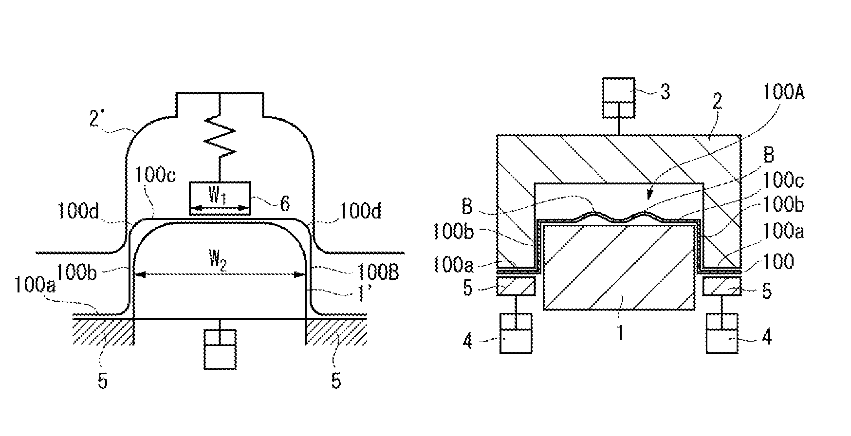
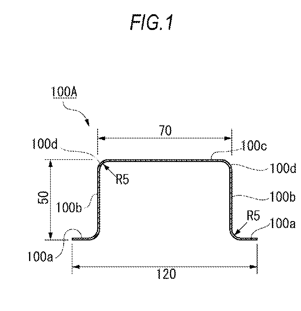
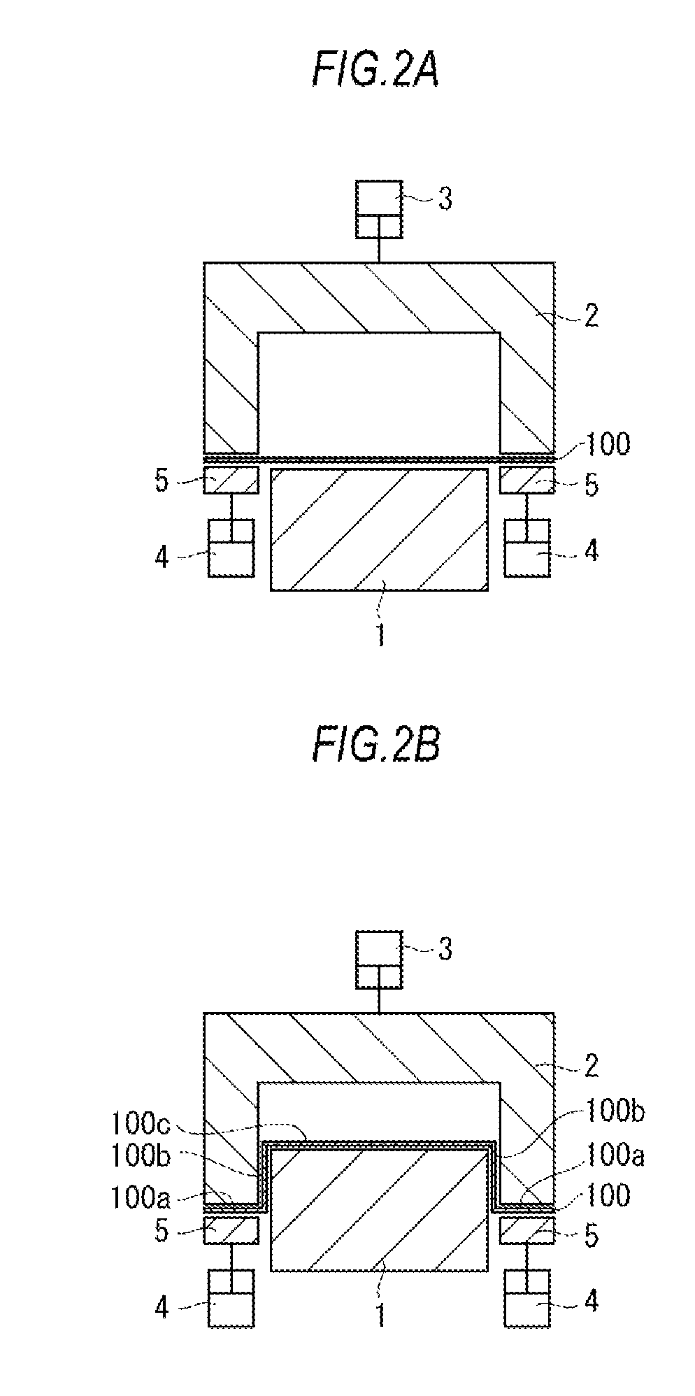
[0099]In this Example, a 590-MPa-class dual phase steel sheet of 1.2 mm thick was prepared as the sheet metal 100, the steel sheet was stamped in the first step into the intermediate shape (intermediate molding), and the intermediate molding was stamped in the second step into the final shape, to thereby manufacture the stamped product having the hat-like cross sectional shape illustrated in FIG. 1. In the first step of press forming, the press forming was conducted while setting the radius R of the stamped shoulder of the intermediate shape (intermediate molding) 1 mm smaller than that of the final shape (stamped product).

[0100]The thus-manufactured stamped product having the hat-like cross sectional shape was butted with a...

example 2

[0132]The effects of the present invention will be more clarified below referring to Example. Note that the present invention is not limited to Example below, and may be implemented in an appropriately modified manner without departing from the spirit thereof.

[0133]In this Example, a 590-MPa-class dual phase steel sheet of 1.2 mm thick was prepared as the sheet metal 100, and the steel sheet was stamped by a press forming method of the present invention illustrated in FIG. 8, FIG. 9A and FIG. 9B, thereby the stamped product having the hat-like cross sectional shape illustrated in FIG. 1 was manufactured.

[0134]In the first step illustrated in FIG. 8, embossments of 10 mm in diameter and 3 mm in height were provided so as to align two in the width-wise direction and 30 in the longitudinal direction. In the second step illustrated in FIG. 9A and FIG. 9B, all of the embossments were squashed and flattened.

[0135]The thus-manufactured stamped product having the hat-like cross sectional sh...


PUM

PropertyMeasurementUnit
lengthaaaaaaaaaa
tensile strengthaaaaaaaaaa

Abstract

Disclosed is a press forming method press forming a workpiece between a die and a punch, while pushing the punch into the die by means of a relative motion of the die and the punch, the method includes: producing an intermediate molding (100B) having ridges (100d) formed in predetermined parts of the workpiece, and then press forming the intermediate molding (100B) into a final shape, to thereby substantially thicken and work-harden the predetermined parts of the workpiece.

Description

[0001]This application is a national stage application of International Application No. PCT / JP2012 / 062522, filed May 16, 2012, which claims priority to Japanese Application Nos. 2011-113629, filed May 20, 2011; and 2011-113630, filed May 20, 2011, each of which is incorporated by reference in its entirety.TECHNICAL FIELD[0002]The present invention relates to a press forming method and a vehicle component.BACKGROUND ART[0003]In recent years, improvement in vehicle fuel efficiency has been an urgent issue in the automobile industry, in view of reducing CO2 emission causative of global warming. In addition to drastic efforts for reducing the CO2 emission by using substitutive fuels, there are growing needs for measures such as improving mechanical efficiencies of engine, transmission and so forth, and reducing weight of vehicle body. On the other hand, in the situation directed to more tight crash safety regulations, another important issue is to develop a vehicle body excellent in veh...

Claims


Application Information

Patent Timeline
Patent Type & Authority Patents(United States)
IPC IPC(8): B21D22/26B21D35/00B21D22/30B21D24/00B21D53/88
CPCB21D22/26B21D22/30B21D24/005B21D35/006B21D53/88
Inventor YONEMURA, SHIGERUUENISHI, AKIHIROTOYOKAWA, SHINKUWAYAMA, TAKUYAARIGA, TAKASHI
Owner NIPPON STEEL CORP
Why Eureka
Try Eureka