
Power conversion apparatus and power conversion method based on a control constant and a feedback value based on current flow

a technology of power conversion apparatus and current flow, which is applied in the direction of power conversion system, dc-dc conversion, instruments, etc., can solve the problem of difficulty in high-adjustable control of transmitted power, and achieve the effect of high accuracy

Inactive Publication Date: 2016-12-06
TOYOTA JIDOSHA KK
View PDF15 Cites 0 Cited by
  • Summary
  • Abstract
  • Description
  • Claims
  • Application Information

AI Technical Summary

Benefits of technology

Enables high-accuracy control of transmitted power even when port currents are significantly changed, ensuring precise power conversion by dynamically adjusting the phase difference with a control constant tailored to current conditions.

Problems solved by technology

However, in the feedback disclosed in JP 2011-193713, since a target value of current flowing to a port is not determined, if the current flowing to the port is greatly changed, it may be difficult to control the transmitted power with high accuracy.

Method used


Image

  • Power conversion apparatus and power conversion method based on a control constant and a feedback value based on current flow
  • Power conversion apparatus and power conversion method based on a control constant and a feedback value based on current flow
  • Power conversion apparatus and power conversion method based on a control constant and a feedback value based on current flow

Examples


Embodiment Construction

101>

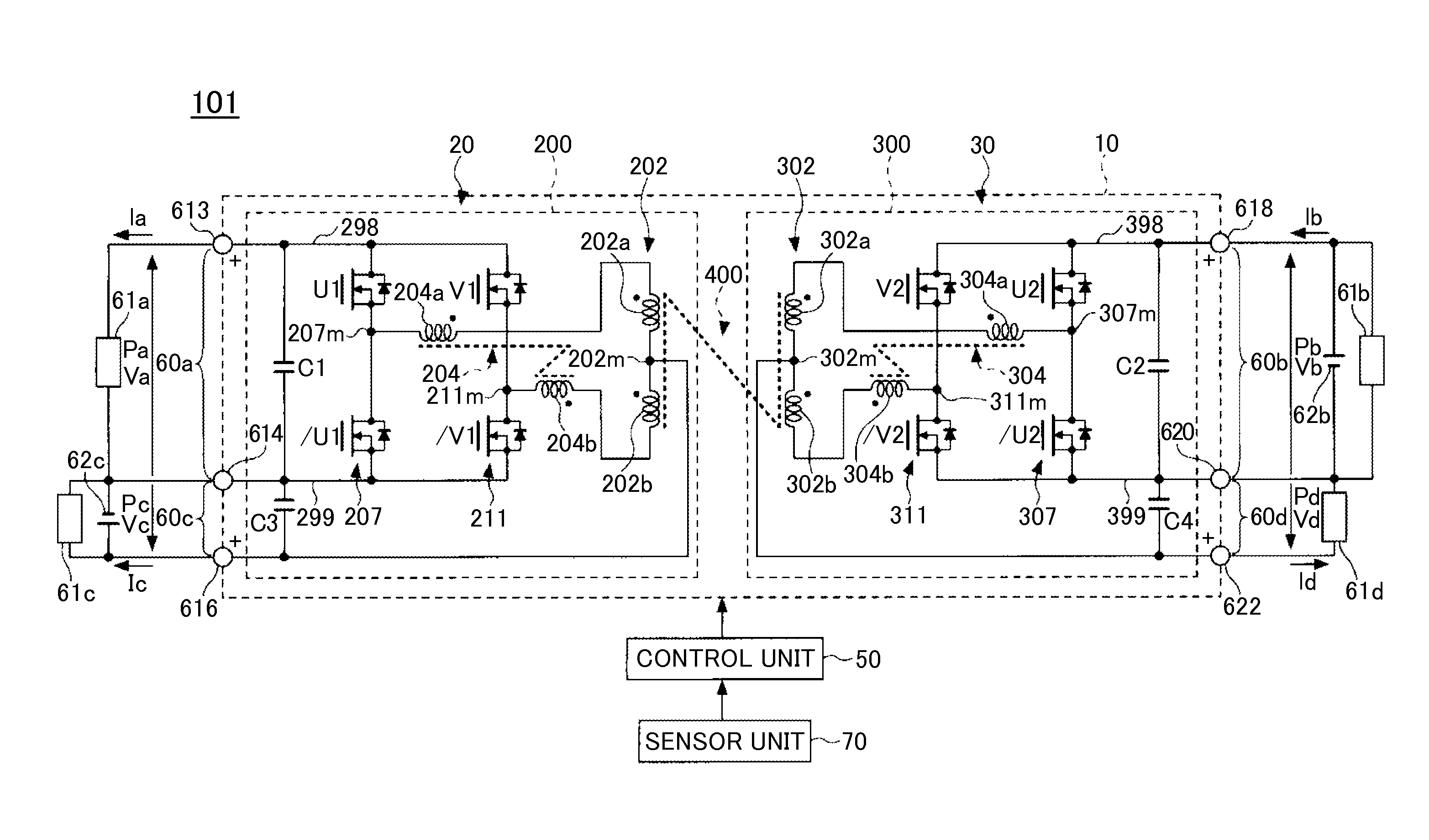
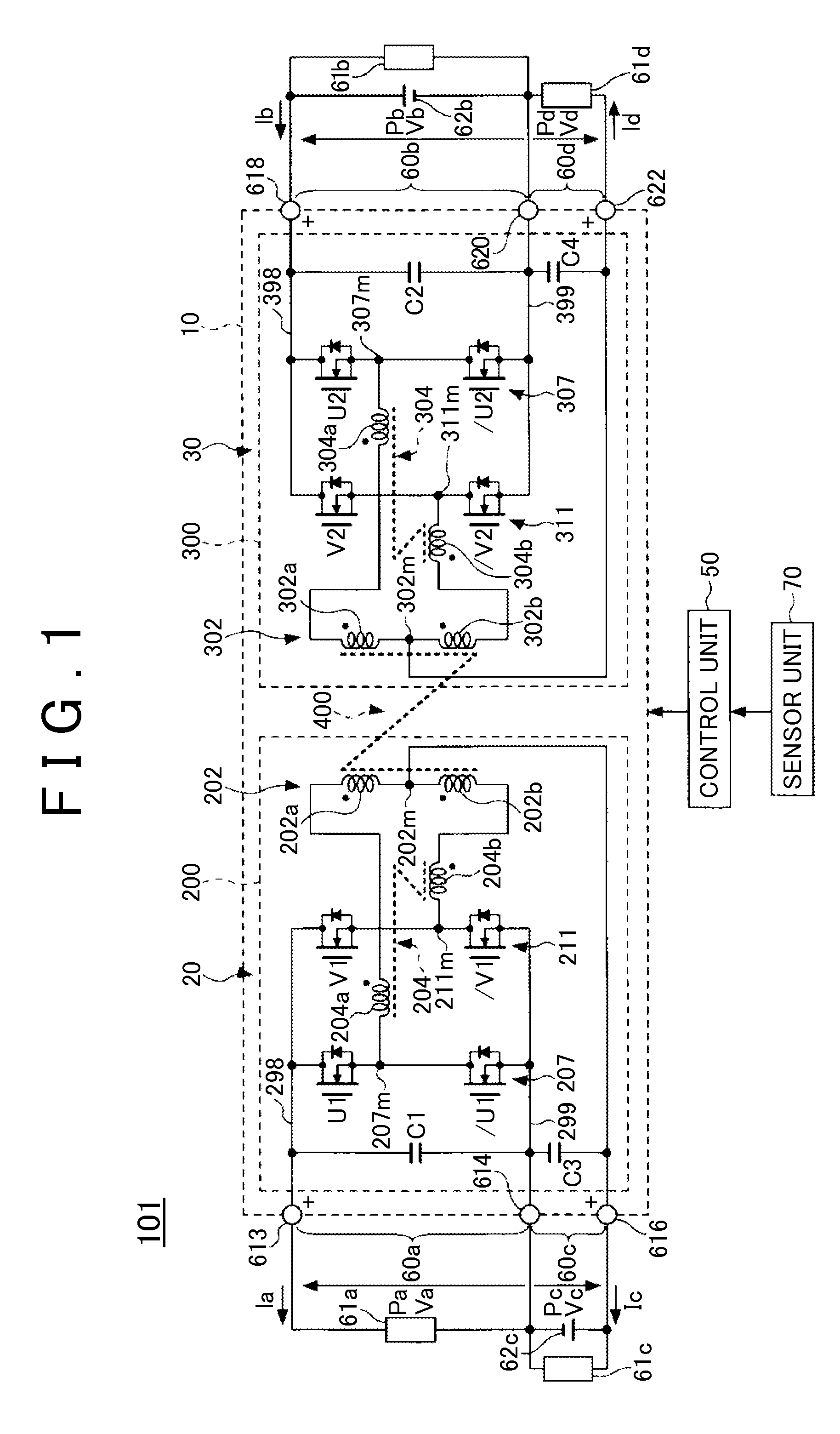
[0016]FIG. 1 is a block diagram showing an example of a configuration of a power supply apparatus 101 which is an embodiment of a power conversion apparatus.

[0017]For example, the power supply apparatus 101 is a power supply system that includes a power supply circuit 10, a control unit 50 and a sensor unit 70. For example, the power supply apparatus 101 is a system that is mounted on a vehicle such as an automobile, and distributes power to various loads of the vehicle. A hybrid vehicle, a plug-in hybrid vehicle, an electric vehicle, and so on may be cited as specific examples of this vehicle. The power supply apparatus 101 may also be mounted on a vehicle using an engine as a driving source.

[0018]For example, the power supply apparatus 101 includes, as primary side ports, a first input / output port 60a to which a primary side high voltage system load 61a is connected and a second input / output port 60c to which a primary side low voltage system load 61c and a primary side low vo...


PUM


Abstract

A power conversion apparatus includes a primary side circuit having a primary side port; a secondary side circuit having a secondary side port; and a control unit that derives a control constant suitable for a feedback value according to a relationship rule between the feedback value and the control constant, and adjusts a phase difference between the primary side circuit and the secondary side circuit using the control constant that is derived from the relationship rule, so as to control transmitted power that is transmitted between the primary side circuit and the secondary side circuit, wherein the feedback value is obtained based on current flowing to the primary side port or the secondary side port.

Description

INCORPORATION BY REFERENCE[0001]The disclosure of Japanese Patent Application No. 2013-245385 filed on Nov. 27, 2013 including the specification, drawings and abstract is incorporated herein by reference in its entirety.BACKGROUND OF THE INVENTION[0002]1. Field of the Invention[0003]The present invention relates to a technique for converting power.[0004]2. Description of Related Art[0005]A power conversion apparatus for converting power between a primary side port of a primary side circuit and a secondary side port of a secondary side circuit is known (see Japanese Patent Application Publication No. 2011-193713 (JP 2011-193713 A), for example). The power conversion apparatus adjusts a phase difference φ between the primary side circuit and the secondary side circuit by feeding back transmitted power PDD transmitted between the primary side circuit and the secondary side circuit in such a manner that the transmitted power PDD becomes command transmitted power PDD*.SUMMARY OF THE INVE...

Claims


Application Information

Patent Timeline
Patent Type & Authority Patents(United States)
IPC IPC(8): H02M3/337H02M3/335
CPCH02M3/3378H02M3/33576H02M3/33546H02M3/33553
Inventor YAMAMOTO, TAKUYA
Owner TOYOTA JIDOSHA KK
Learn More