
Laminated and ion-exchanged strengthened glass laminates

a technology of reinforced glass and laminates, which is applied in the direction of glass making apparatus, manufacturing tools, transportation and packaging, etc., can solve the problems of ineffective thermal tempered glass, thin glasses, less than 2 mm thick, and easy damage to glass articles incorporated in these devices, and achieve the effect of enhancing compressive stress

Active Publication Date: 2016-12-20
CORNING INC
View PDF93 Cites 44 Cited by
  • Summary
  • Abstract
  • Description
  • Claims
  • Application Information

AI Technical Summary

Benefits of technology

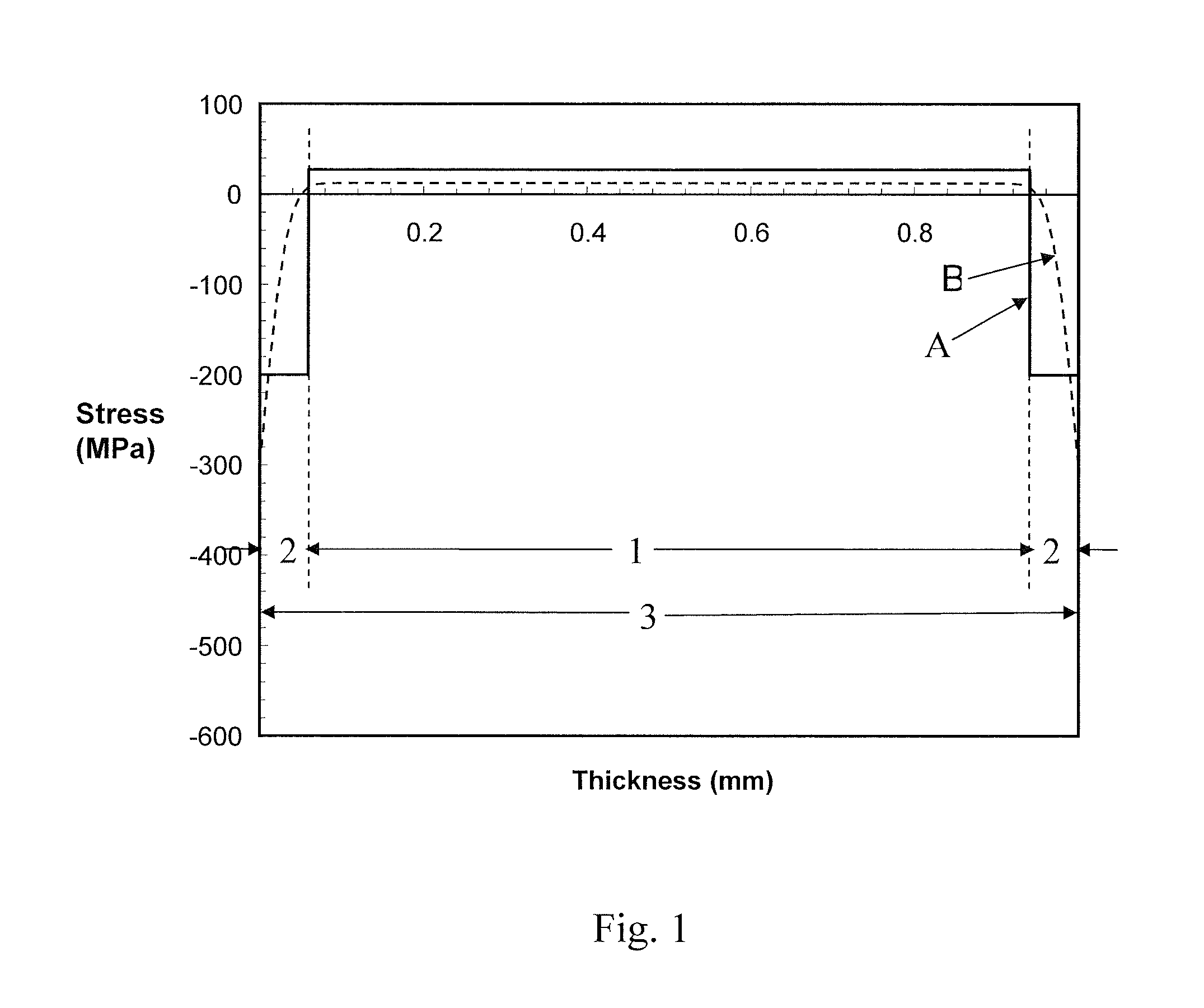
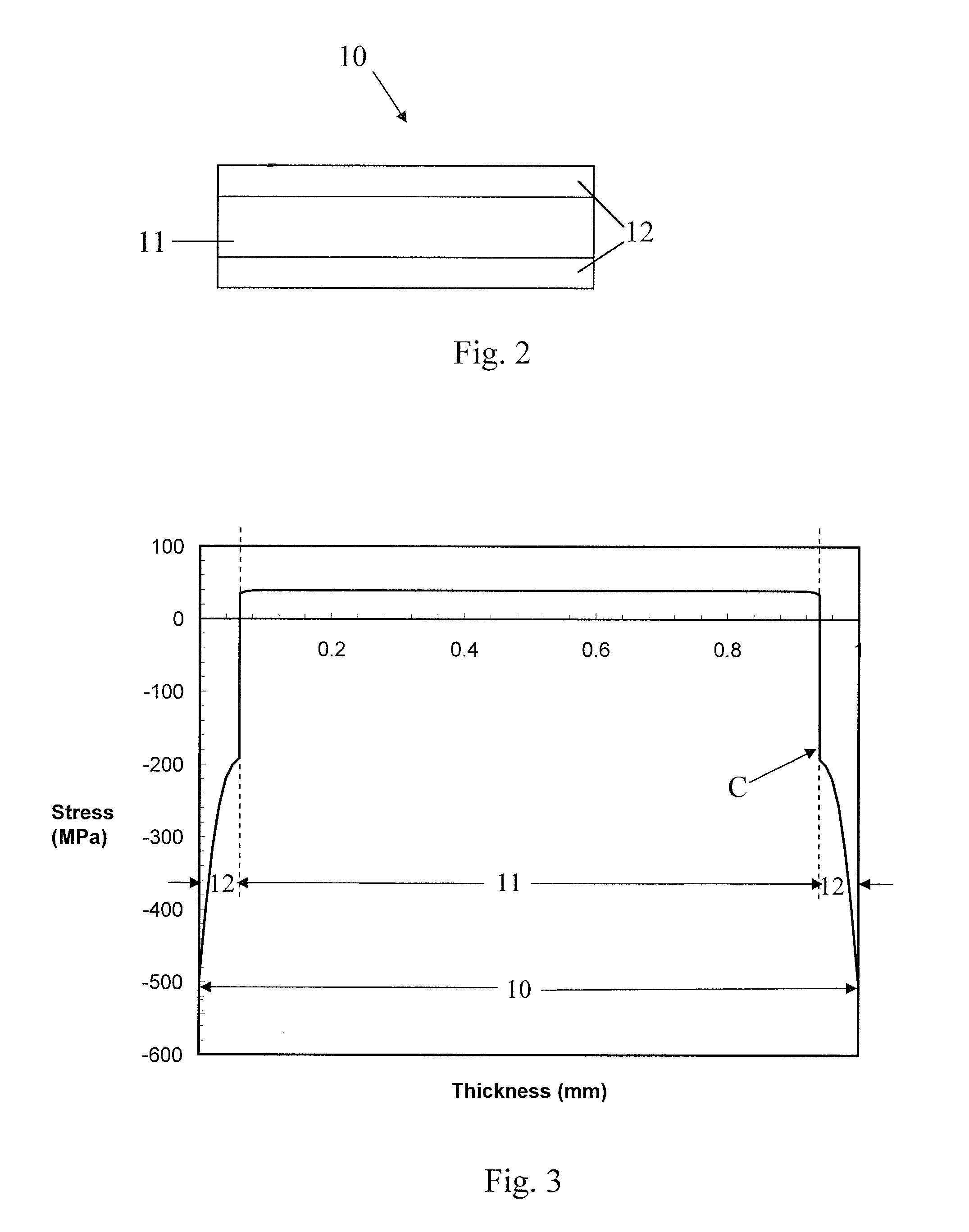
This patent describes how to create strong glass using both mechanical strengthening and ion exchange chemical strengthening. The resulting glass has a higher combination of compressive stress and depth of compressive stress layer than either process alone. The glass can be used for a variety of applications where it is exposed to harsh conditions. Another embodiment involves a strengthened laminated glass structure with a core glass layer and at least one ion exchangeable clad glass layer. The clad glass layer is in a state of compressive stress, and the outer surface region is in a state of enhanced compressive stress.

Problems solved by technology

The glass articles incorporated in these devices may be susceptible to damage during transport and / or use of the associated device.
Once a fracture propagates all the way through the near surface region of the glass that is under compressive stress (i.e. through the depth of layer) and the tip of the crack reaches the inner portion of the glass sheet or laminate that is under tension, then the crack quickly propagates through the glass resulting in a sudden failure and the glass product shatters.
Thin glasses, less than 2 mm thick, cannot be effectively tempered thermally.
Silicate glasses that can be laminated do not develop sufficient surface compressive stress due to limited amount of expansion differential between the clad glass and core glass.
This level of compression is inadequate for some applications, i.e. for mitigating impact stresses in day to day use.

Method used


Image

  • Laminated and ion-exchanged strengthened glass laminates
  • Laminated and ion-exchanged strengthened glass laminates
  • Laminated and ion-exchanged strengthened glass laminates

Examples


Embodiment Construction

[0039]In the following description, like reference characters designate like or corresponding parts throughout the several views shown in the figures. It is also understood that, unless otherwise specified, terms such as “top,”“bottom,”“outward,”“inward,” and the like are words of convenience and are not to be construed as limiting terms that limit the invention to any particular orientation. Unless otherwise specified, a range of values, when recited, includes both the upper and lower limits of the range, as well as any sub-ranges there between.

[0040]The term “liquidus viscosity,” as used herein, refers to the shear viscosity of the glass composition at its liquidus temperature.

[0041]The term “liquidus temperature,” as used herein, refers to the highest temperature at which devitrification occurs in the glass composition.

[0042]The term “CTE,” as used herein, refers to the coefficient of thermal expansion of the glass composition averaged over a temperature range from about 20° C. t...


PUM

PropertyMeasurementUnit
thicknessaaaaaaaaaa
thicknessaaaaaaaaaa
total thicknessaaaaaaaaaa

Abstract

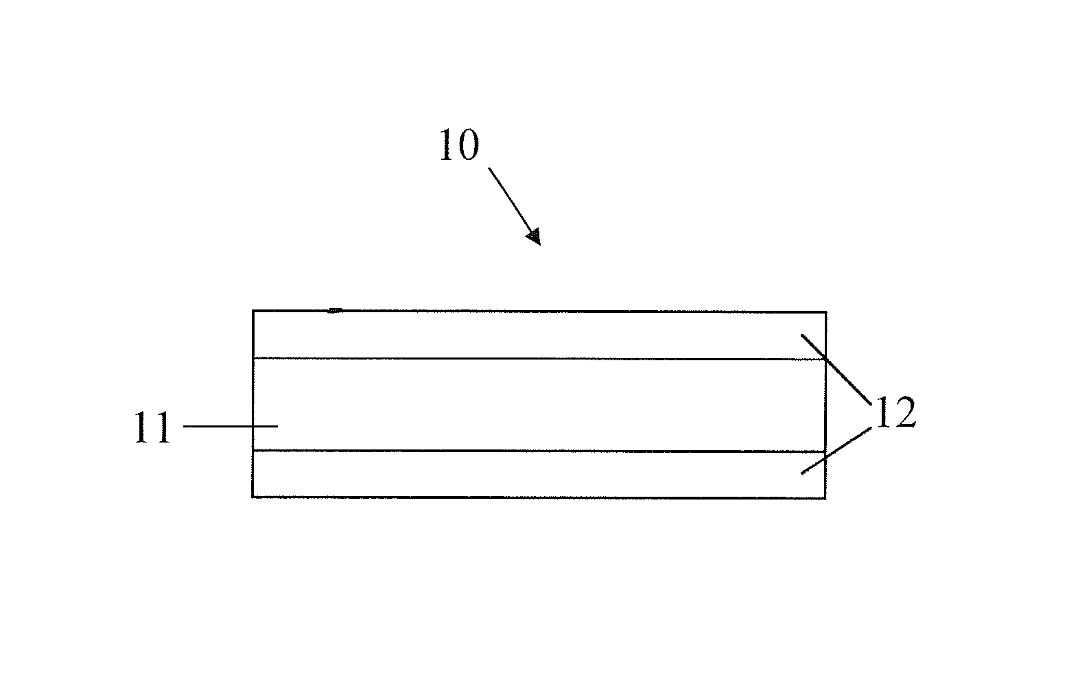
A method of making a glass sheet (10) comprises laminating a high CTE core glass (11) to a low CTE clad glass (12) at high temperatures and allowing the laminate (10) to cool creating compressive stress in the clad glass (12), and then ion exchanging the laminate (10) to increase the compressive stress in the outer near surface regions of the clad glass (12). The core glass (11) may include ions that exchange with ion in the clad glass (12) to increase the compressive stress in inner surface regions of the clad glass (12) adjacent to the clad glass / core glass interfaces. The glass laminate (10) may be formed and laminated using a fusion forming and laminating process and fusion formable and ion exchangeable glass compositions.

Description

CROSS-REFERENCE TO RELATED APPLICATIONS[0001]This application claims the benefit of priority under 35 U.S.C. §119 of U.S. Provisional Application Ser. No. 61 / 511,422 filed on Jul. 25, 2011, the entire content of which is hereby incorporated by reference.BACKGROUND[0002]Field[0003]The disclosure relates generally to ion exchanged thin glass laminates, and more particularly ion exchanged thin glass laminates having a low coefficient of thermal expansion (CTE) ion-exchanged glass outer clad glass layer(s) laminated onto a high CTE glass inner core glass layer for creating compressive stresses in the outer clad glass layer(s), and more particularly to such laminates that have been strengthened via ion exchange, and more particularly to glass fusion forming and laminating processes and glass compositions for making such laminates, which may be used in automotive, aviation, architectural, appliance, display, touch panel, and other applications where a thin, strong, scratch resistant glass...

Claims


Application Information

Patent Timeline
Patent Type & Authority Patents(United States)
IPC IPC(8): C03B17/02B32B17/06C03C21/00C03B17/06C03C3/093C03B23/20C03B29/02C03C3/091
CPCC03B17/02B32B17/06C03B17/025C03B17/06C03B17/064C03B23/20C03B29/025C03C3/091C03C3/093C03C21/002Y10T428/24942Y10T428/2933B32B2307/30C03C3/085C03C3/087C03C4/18C03C2204/00
Inventor GULATI, SURESH THAKORDASGALLAGHER, MICHAEL THOMASKICZENSKI, TIMOTHY JAMESSCHAUT, ROBERT ANTHONYVENKATARAMAN, NATESAN
Owner CORNING INC
Learn More