Rotorcraft with a fuselage and at least one main rotor

a technology of fuselage and main rotor, which is applied in the direction of sustainable transportation, transportation and packaging, and efficient propulsion technologies, can solve the problems of comparatively low maintenance effort of inventive passive wing-type aerodynamic devices, and achieve the effects of reducing power consumption, advantageously increasing the main rotor, and expanding the flight envelope of the rotorcra

Active Publication Date: 2016-12-27
AIRBUS HELICOPTERS DEUT GMBH
View PDF47 Cites 13 Cited by
  • Summary
  • Abstract
  • Description
  • Claims
  • Application Information

AI Technical Summary

Benefits of technology

[0025]The inventive passive wing-type aerodynamic device is preferably mounted to the fuselage for passively rotating relative thereto, i.e. it is able to rotate in a free-floating manner relative to the fuselage. More specifically, the inventive passive wing-type aerodynamic device is a passive device that requires no actuator, thereby avoiding the weight and the need for redundancy of an active system. Accordingly, a required maintenance effort for the inventive passive wing-type aerodynamic device will be comparatively low.
[0027]Furthermore, with the inventive passive wing-type aerodynamic device the unloading of the main rotor advantageously increases with flight speed in operation. This unloading has its highest peak at a high-speed end of the flight envelope of the rotorcraft, where rotor thrust limits of the main rotor are approached if no such passive wing-type aerodynamic device is present.
[0028]The unloading of the main rotor is beneficial, as it reduces power consumption and / or allows expanding the flight envelope of the rotorcraft towards higher flight speeds and altitudes. Moreover, the unloading of the main rotor allows reducing a respective rotational speed of the main rotor in operation. This further amplifies gains in power consumption, as the power expended in overcoming profile drag is reduced.
[0029]Moreover, the inventive passive wing-type aerodynamic device avoids a vertical drag penalty in hover, as the passive wing-type aerodynamic device rotates in a self-actuating manner into a hover rotational orientation, i.e. it self-adjusts its rotational orientation into an approximately vertical orientation, such that it virtually generates no down force. Thereby, a rearward facing force generated by the passive wing-type aerodynamic device in its hover rotational orientation is easily counteracted by a small forward tilt of a respective rotor thrust vector, i.e. a small longitudinal control input by the pilot.
[0049]Advantageously, the positioning of the passive wing-type aerodynamic devices opens up a design space: With a given aerodynamic pitching moment requirement, the amount of lift or off-loading of the main rotor can be controlled by the choice of the positioning of the passive wing-type aerodynamic devices relative to the fuselage of the rotorcraft. Full benefit of an associated thrust reduction is then taken by additionally reducing a corresponding rotational speed of the main rotor. This reduces the power expended in overcoming a respective profile drag of the rotor blades of the main rotor.

Problems solved by technology

Accordingly, a required maintenance effort for the inventive passive wing-type aerodynamic device will be comparatively low.

Method used


Image

  • Rotorcraft with a fuselage and at least one main rotor
  • Rotorcraft with a fuselage and at least one main rotor
  • Rotorcraft with a fuselage and at least one main rotor

Examples


Embodiment Construction

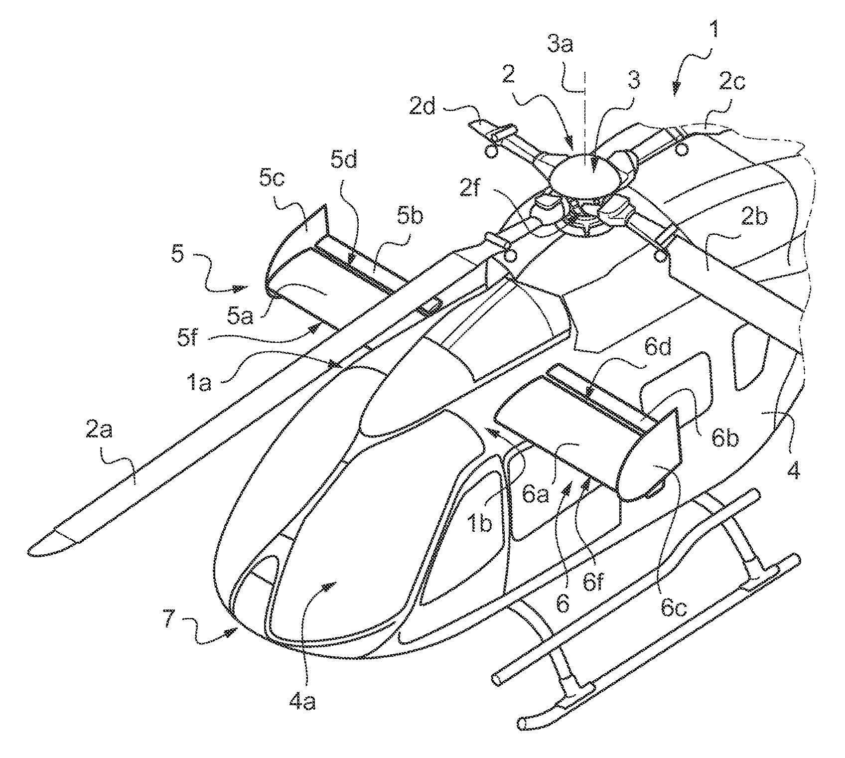
[0074]FIG. 1 shows a rotorcraft 1 with a fuselage 4 and a main rotor 2. The rotorcraft 1 is illustratively embodied as a helicopter and the main rotor 2 is illustratively embodied as a hingeless or a hinge- and bearingless multi-blade rotor having a plurality of rotor blades 2a, 2b, 2c, 2d. It should, however, be noted that the present invention is not limited to helicopters and may likewise be applied to other aircrafts that are equipped with rotary wings, independent on whether these rotary wings define articulated, hingeless or hinge- and bearingless multi-blade rotors. It should further be noted that the present invention may also be applied in cases where more than one main rotor is provided.

[0075]The main rotor 2 and, thus, the plurality of rotor blades 2a, 2b, 2c, 2d is drivable, i.e. controllable to influence an associated pitch attitude Θ of the rotorcraft 1 in operation, which assumes varying pitch attitudes in operation. Preferably, the main rotor 2 is configured to be dr...


PUM


Abstract

A rotorcraft with a fuselage and at least one main rotor, the at least one main rotor being drivable for controlling an associated pitch attitude of the rotorcraft in operation, and the fuselage being equipped with at least one passive wing-type aerodynamic device that is adapted for generating independently of the associated pitch attitude a lift force acting on the fuselage, the lift force being oriented perpendicular to an air flow that is directed in operation of the rotorcraft against the passive wing-type aerodynamic device.

Description

CROSS REFERENCE TO RELATED APPLICATION[0001]This application claims priority to European patent application No. EP 14 400004.9 filed on Jan. 27, 2014, the disclosure of which is incorporated in its entirety by reference herein.BACKGROUND OF THE INVENTION[0002](1) Field of the Invention[0003]The invention is related to a rotorcraft with a fuselage and at least one main rotor, said rotorcraft comprising the features of claim 1.[0004](2) Description of Related Art[0005]A rotorcraft with a single main rotor and a fuselage defining a cabin and a tail boom of the rotorcraft features in operation an inherent aerodynamic nose-down pitching moment about a rotor center of the single main rotor, with the rotor center as reference point of moments. The aerodynamic nose-down pitching moment is an “aerodynamic” load that results from a given main rotor downwash and an airflow, which is due to forward flight in operation and which increases with a corresponding velocity of a given incoming air flo...

Claims


Application Information

Patent Timeline
Patent Type & Authority Patents(United States)
IPC IPC(8): B64C5/16B64C3/38B64C27/04B64C27/82
CPCB64C5/16B64C3/385B64C27/04B64C27/82B64C2027/8236Y02T50/145Y02T50/10
Inventor EMBACHER, MARTIN
Owner AIRBUS HELICOPTERS DEUT GMBH
Why Eureka
Try Eureka