Rotary internal combustion engine with pilot subchamber

a technology of internal combustion engine and pilot subchamber, which is applied in the direction of combination engine, rotary piston engine, rotary or oscillating piston engine, etc., and can solve problems such as unoptimized known arrangemen

Active Publication Date: 2016-12-27
PRATT & WHITNEY CANADA CORP
View PDF80 Cites 38 Cited by
  • Summary
  • Abstract
  • Description
  • Claims
  • Application Information

AI Technical Summary

Benefits of technology

[0004]Rotary engines come in many forms. One well-known type, the Wankel engine, has a generally triangular rotor received in a two-lobed epitrochoid cavity. Other non-Wankel rotary engines types exist as well. However, known arrangements are not optimized, in terms of combustion arrangements and characteristics, and thus room for improvement exists.

Problems solved by technology

However, known arrangements are not optimized, in terms of combustion arrangements and characteristics, and thus room for improvement exists.

Method used


Image

  • Rotary internal combustion engine with pilot subchamber
  • Rotary internal combustion engine with pilot subchamber
  • Rotary internal combustion engine with pilot subchamber

Examples


Embodiment Construction

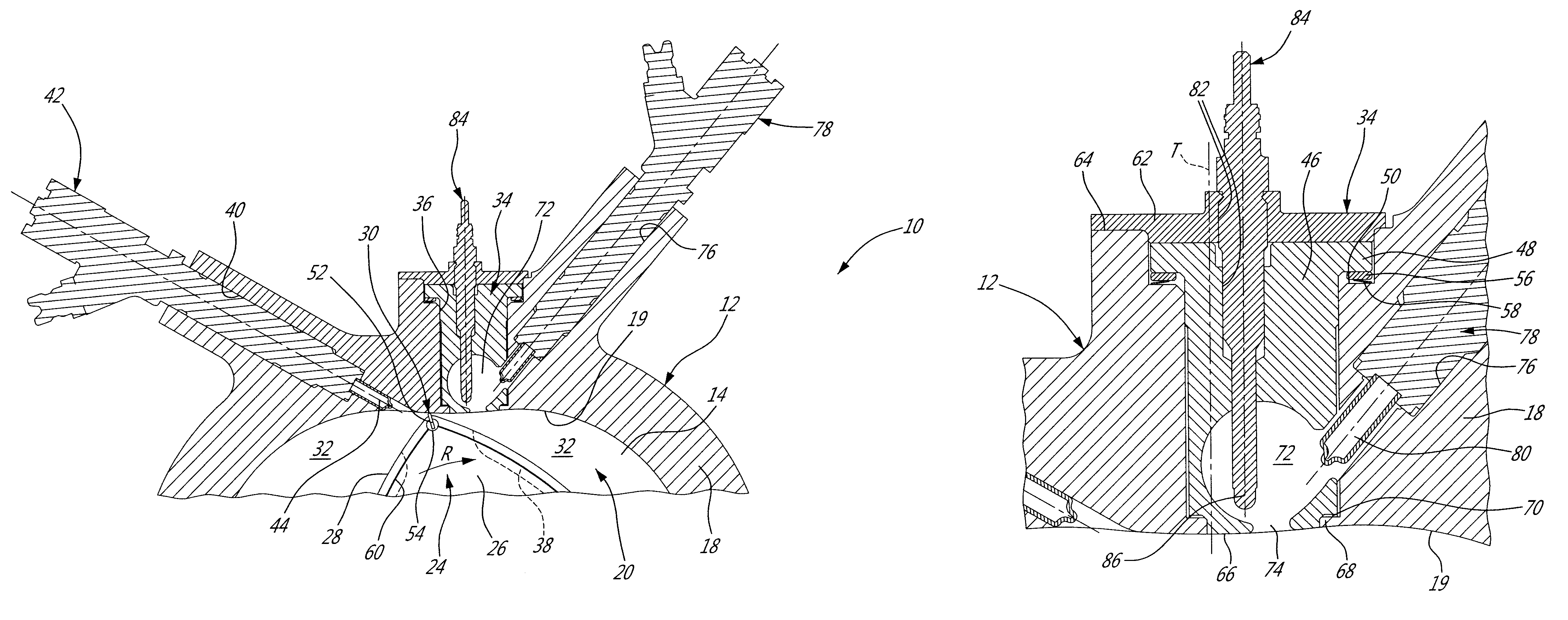
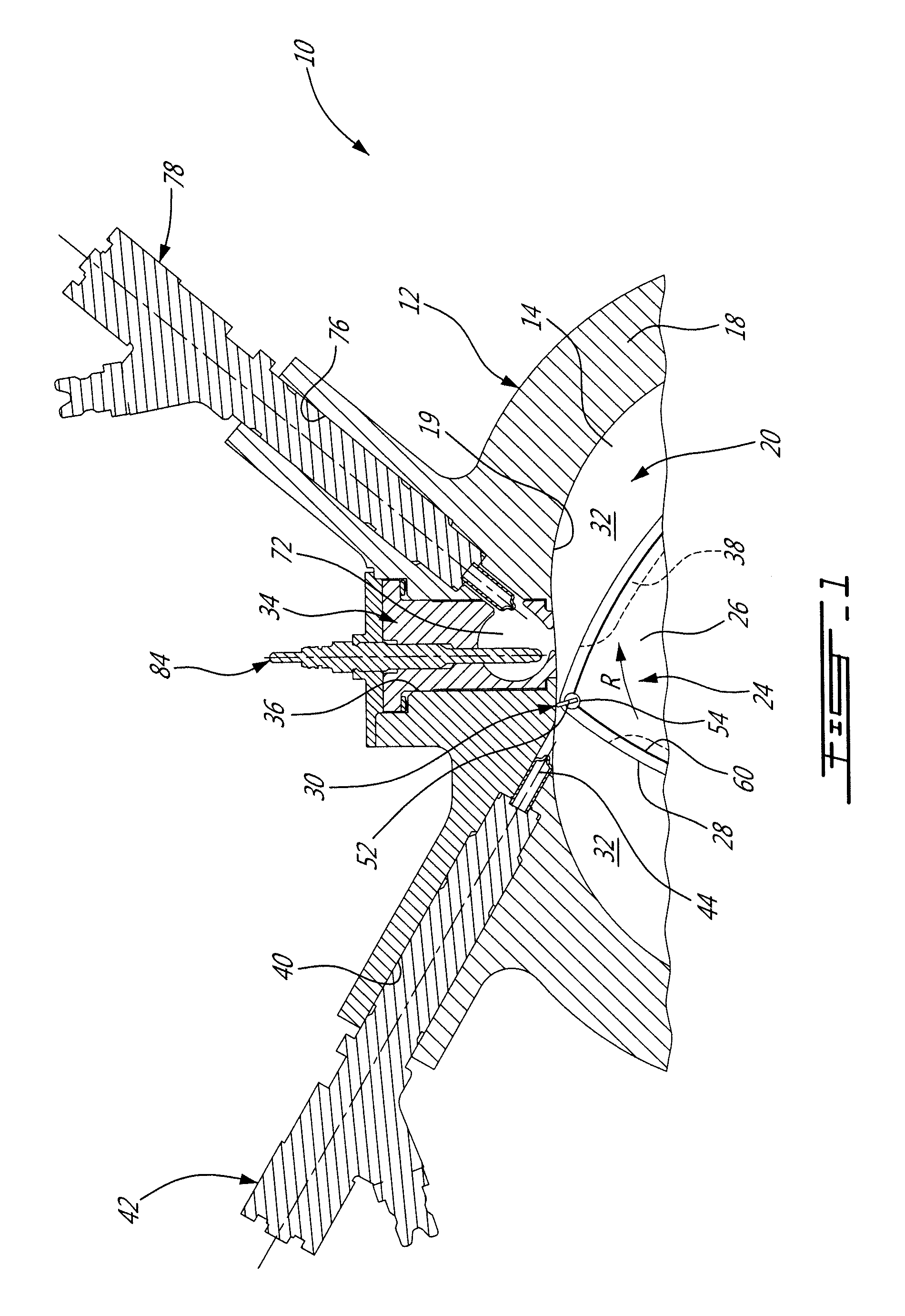
[0018]Referring to FIG. 1, a rotary internal combustion engine 10 known as a Wankel engine is schematically and partially shown. In a particular embodiment, the rotary engine 10 is used in a compound cycle engine system such as described in Lents et al.'s U.S. Pat. No. 7,753,036 issued Jul. 13, 2010 or as described in Julien et al.'s U.S. Pat. No. 7,775,044 issued Aug. 17, 2010, the entire contents of both of which are incorporated by reference herein. The compound cycle engine system may be used as a prime mover engine, such as on an aircraft or other vehicle, or in any other suitable application. In any event, in such a system, air is compressed by a compressor before entering the Wankel engine, and the engine drives one or more turbine(s) of the compound engine. In another embodiment, the rotary engine 10 is used without a turbocharger, with air at atmospheric pressure.

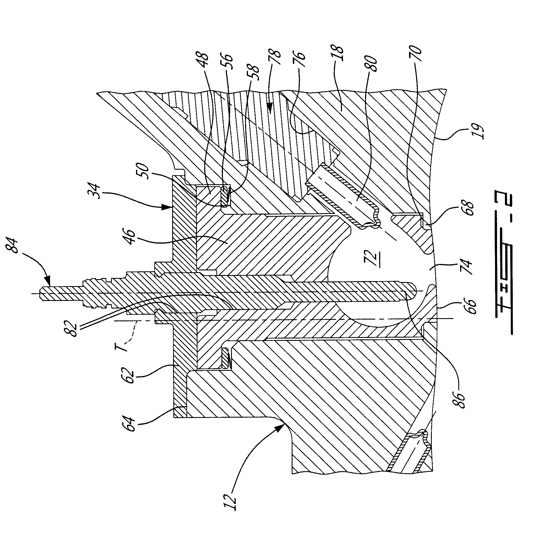
[0019]The engine 10 comprises an outer body 12 having axially-spaced end walls 14 with a peripheral wall 18 exte...


PUM


Abstract

A non-Wankel rotary engine having an insert in the peripheral wall of the outer body, the insert being made of a material having a greater heat resistance than that of the peripheral wall, having a subchamber defined therein and having an inner surface bordering the cavity, the subchamber communicating with the cavity through at least one opening defined in the inner surface and having a shape forming a reduced cross-section adjacent the opening, a pilot fuel injector having a tip received in the subchamber, an ignition element having a tip received in the subchamber, and a main fuel injector extending through the housing and having a tip communicating with the cavity at a location spaced apart from the insert.

Description

CROSS-REFERENCE TO RELATED APPLICATIONS[0001]This application is a continuation-in-part of U.S. application Ser. No. 13 / 273,534 filed Oct. 14, 2011, which claims priority on provisional U.S. application No. 61 / 512,593 filed Jul. 28, 2011, the entire contents of which are incorporated by reference herein.TECHNICAL FIELD[0002]The application relates generally to a rotary internal combustion engine.BACKGROUND OF THE ART[0003]Rotary engines, such as for example Wankel engines, use the rotation of a piston to convert pressure into a rotating motion, instead of using reciprocating pistons. In these engines, the rotor typically includes a number of seals that remain in contact with a peripheral wall of the rotor cavity of the engine throughout the rotational motion of the rotor to create a plurality of rotating chambers when the rotor rotates.[0004]Rotary engines come in many forms. One well-known type, the Wankel engine, has a generally triangular rotor received in a two-lobed epitrochoid...

Claims


Application Information

Patent Timeline
Patent Type & Authority Patents(United States)
IPC IPC(8): F02C5/00F02B53/10
CPCF02B53/10F01C1/22F01C11/006F01C20/06F01C20/10F01C20/24F01C21/06F01C21/08F01C21/106F01C21/18F01C21/183F02B19/10F02B19/108F02B19/12F02B19/165F02B53/02F02B53/12F02B55/08F04C29/0092F04C2240/80Y02T10/12
Inventor THOMASSIN, JEANDAVENPORT, NIGELGEKHT, EUGENE
Owner PRATT & WHITNEY CANADA CORP
Why Eureka
Try Eureka