Hand-held power tool with an internal combustion engine

a technology of internal combustion engine and power tool, which is applied in the direction of machines/engines, percussive tools portable, charge feed systems, etc., can solve the problem of low weight of power tools, and achieve the effect of simple and robust configuration, favorable introduction, and simple and robust configuration

Active Publication Date: 2016-12-27
ANDREAS STIHL AG & CO KG
View PDF11 Cites 3 Cited by
  • Summary
  • Abstract
  • Description
  • Claims
  • Application Information

AI Technical Summary

Benefits of technology

[0004]It is an object of the present invention to provide a hand-held power tool with an internal combustion engine of the aforementioned kind that enables ergonomic handling.
[0006]For restoring the operating mode selector, a restoring element is provided that is permanently coupled to the position of the throttle trigger. When the throttle trigger is actuated for release of the locking action, the restoring element is acting on the operating mode selector and restores the operating mode selector from the start position into the operating position. The operating mode selector is thereby not restored by means of spring forces acting on the operating mode selector and on the throttle element into the operating position, but instead by the restoring element as a result of the force applied by the operator on the throttle trigger. In this way, no great spring forces must be provided on the throttle element and on the operating mode selector. Even in case of unfavorable ratios of the leverage lengths of the coupling elements that transmit the spring forces acting on the throttle element onto the operating mode selector, a safe restoring action of the operating mode selector can be achieved. The coupling elements between the operating mode selector and the throttle element must not be designed for transmission of great forces so that a simple configuration and, as a whole, a low weight of the power tool will result.
[0007]Advantageously, the restoring element interacts with an actuating part which is connected to the operating mode selector. The restoring element is in particular pivotably supported on the throttle trigger and is resting on the actuating part. Due to the pivotable support of the restoring element on the throttle trigger, a constructively simple configuration results. The restoring element in this context is in particular a separate component that is pivotably supported on the throttle trigger. The restoring element can be advantageously also designed to be a monolithic part together with the throttle trigger, for example, when throttle trigger and restoring element are made of plastic material. By means of appropriate minimal wall thickness, elasticity of the connection of throttle trigger and restoring element and, in this way, a pivotability of the restoring element relative to the throttle trigger can be achieved. It may also be provided that the restoring element is arranged to be lengthwise slidable relative to the throttle trigger and is actuated, for example, by means of a cam or the like of the throttle trigger.
[0011]Advantageously, the deflecting section is lifted off the restoring element upon adjustment of the operating mode selector from the operating position into the start position. Accordingly, it is made possible in a simple way that the restoring element can pivot and that the restoring section is moved into the movement path of the restoring element. The actuating part has advantageously a contact section which deflects the restoring element when the throttle trigger is in its full throttle position and the operating mode selector is in its start position. Upon pivoting of the throttle trigger into the idle position, the restoring element advantageously slips off the contact section. In this way, it is ensured in a simple way that, for selecting the start position, the throttle trigger can be actuated into the full throttle position without being blocked by the restoring section of the actuating part. Since the restoring element slips off the contact section when the throttle trigger is pivoted, the restoring element is able to pivot such that the restoring section of the actuating part is positioned in the movement path of the restoring element.
[0012]A simple and robust configuration can be achieved when at least one lateral guide for the restoring element is provided. In case of a pivotable restoring element the lateral guide is advantageously positioned transversely to the longitudinal direction of the pivot axis of the restoring element. Expediently, two lateral guides for the restoring element are provided which are positioned opposite each other and guide the restoring element at both sides in the direction of the pivot axis.
[0013]Advantageously, in the intake passage a first throttle element and a second throttle element are arranged wherein both throttle elements are adjusted by means of the operating mode selector into a start position. Advantageously, one of the throttle elements is a throttle element that is actuated by the throttle trigger and the other throttle element is a choke element. Advantageously, the first throttle element is connected to a first coupling lever and the second throttle element is connected to a second coupling lever. In the start position of the operating mode selector, the two coupling levers are advantageously locked with each other and secure the throttle elements in their throttling position. Due to the locking action of the two coupling levers with each other, a simple constructive configuration results. Since no further elements are taking part in the locking action, the tolerances of the locking action can be maintained at a minimal level and the desired positions of the throttle elements in the start position can be adjusted comparatively precisely. The throttle trigger acts advantageously on the first throttle element and the operating mode selector on the second throttle element. The throttle elements can be advantageously throttle flaps or barrel-type throttle elements. The operating mode selector acts advantageously by means of an actuating lever on the second throttle element wherein the actuating lever has a first contact surface and a second contact surface. Upon pivoting of the operating mode selector from the operating position into the start position, the actuating lever advantageously is acting first by means of the first contact surface and then by means of the second contact surface on the second throttle element. The two contact surfaces are advantageously configured as flat surfaces and are positioned angularly relative to each other. In this way, the effective direction of the force, exerted by the operating mode selector by means of the actuating lever on the second throttle element, can be favorably introduced across the entire actuating range.

Problems solved by technology

The coupling elements between the operating mode selector and the throttle element must not be designed for transmission of great forces so that a simple configuration and, as a whole, a low weight of the power tool will result.

Method used


Image

  • Hand-held power tool with an internal combustion engine
  • Hand-held power tool with an internal combustion engine
  • Hand-held power tool with an internal combustion engine

Examples


Embodiment Construction

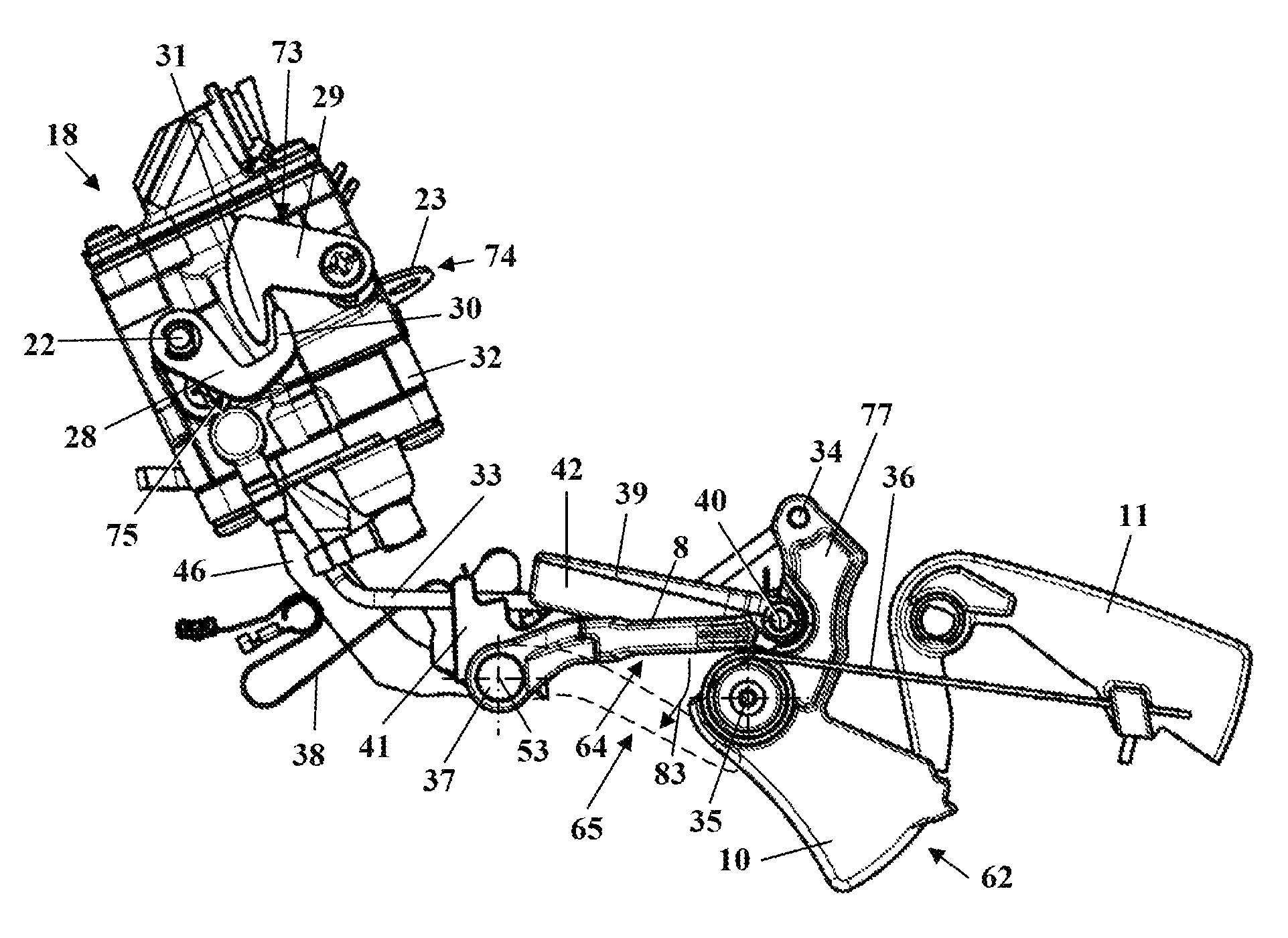
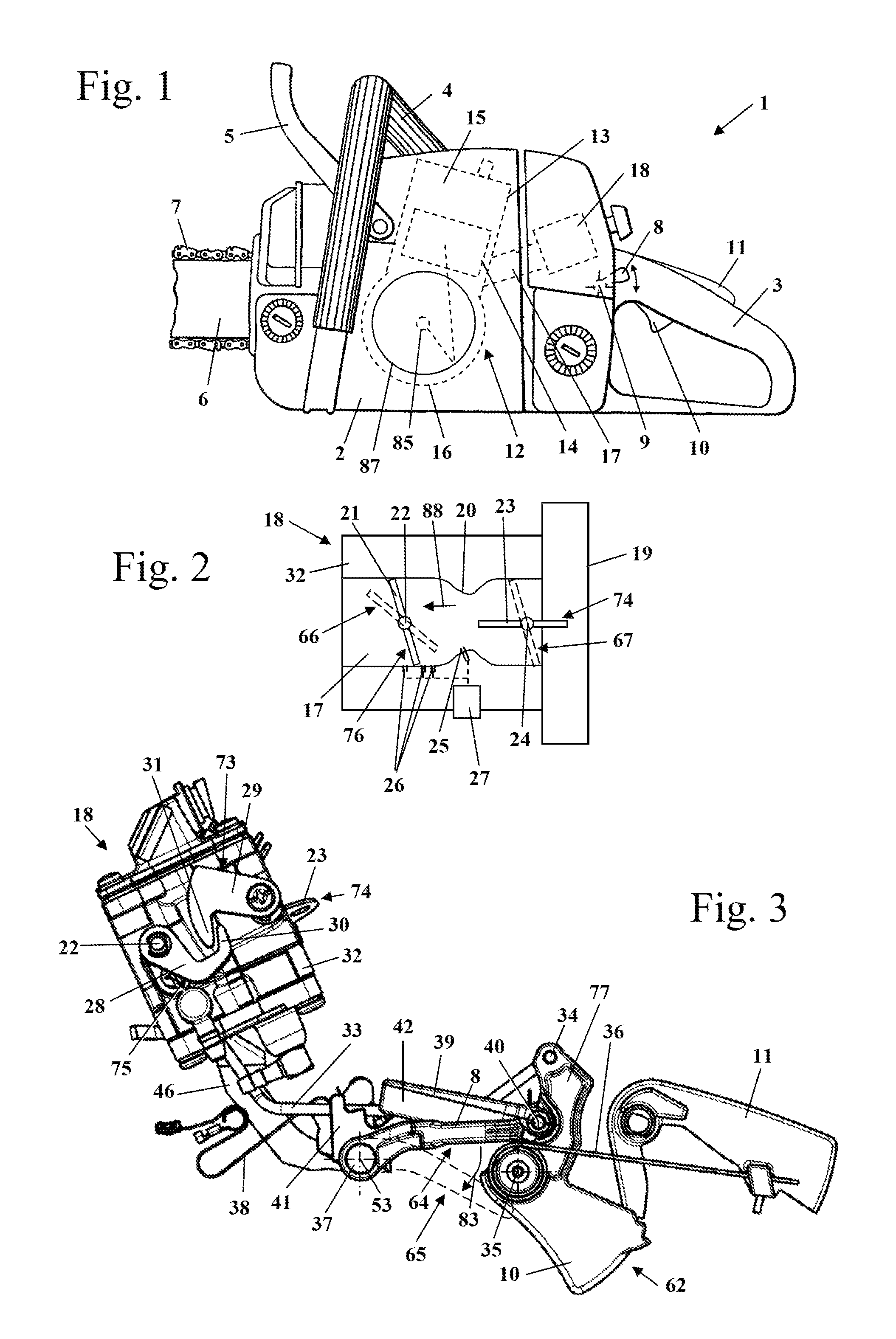
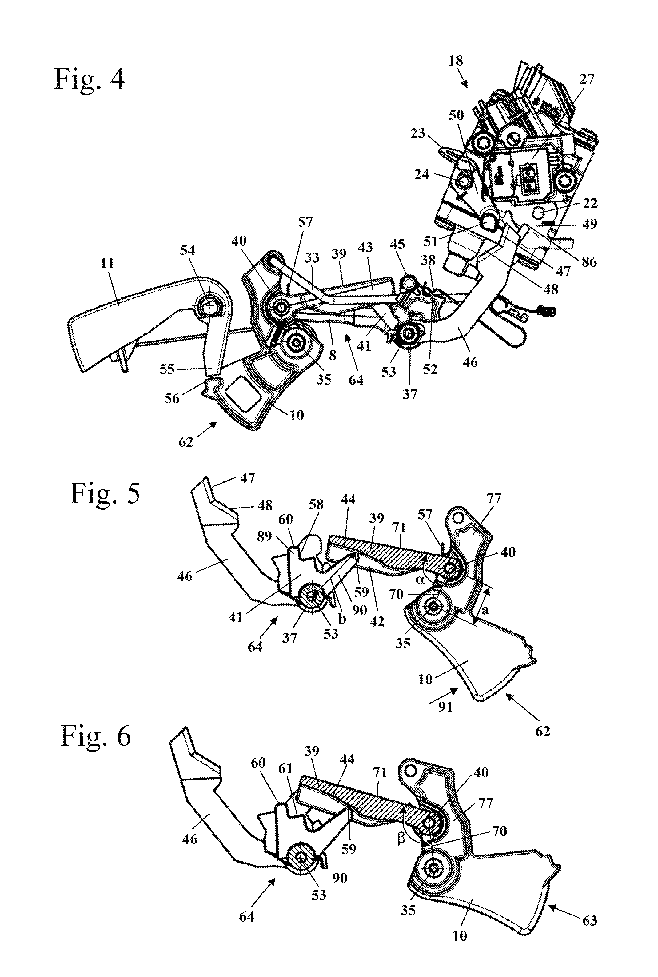
[0025]FIG. 1 shows a motor chain saw 1 as an embodiment of a hand-held power tool. Instead of the motor chain saw 1, a different type of hand-held power tool can be provided such as a cut-off machine, a trimmer, a suction / blowing device, a hedge trimmer, a harvesting device, or the like. The motor chain saw 1 has a housing 2 on which a rear handle 3 and a front handle (grip tube) 4 for guiding the motor chain saw 1 in operation are secured. On the side of the housing 2 which is opposite the rear handle 3, a guidebar 6 projects forwardly on which a saw chain 7 is arranged so as to circulate about the guidebar 6. On the housing 2, a hand guard 5 is arranged which is positioned on the side of the front handle 4 which is facing the saw chain 7. The hand guard 5 can be pivotably supported on the housing 2 and can serve for triggering a chain brake for the saw chain 7.

[0026]The saw chain 7 is driven in circulation by an internal combustion engine 12 arranged within the housing 2. The inte...


PUM


Abstract

A hand-held power tool has an internal combustion engine provided with a throttle trigger adjustable between an idle position and a full throttle position. The engine has an operating mode selector adjustable between an operating position and a start position. In an intake passage of the engine, a throttle element is arranged that is in a throttling position when the operating mode selector is in the start position. The throttle element is secured in the throttling position by a locking action. The locking action is released when the throttle trigger is moved from the idle position toward the full throttle position. A restoring element is coupled permanently to the position of the throttle trigger. The restoring element, when the throttle trigger is moved for releasing the locking action, acts on the operating mode selector and restores the operating mode selector from the start position into the operating position.

Description

BACKGROUND OF THE INVENTION[0001]The invention relates to a hand-held power tool with an internal combustion engine, comprising a throttle trigger and an operating mode selector, wherein the throttle trigger is adjustable between an idle position and a full throttle position and wherein the operating mode selector is adjustable between an operating position and a start position, wherein the internal combustion engine has an intake passage in which at least one throttle element is arranged, wherein the throttle element in the start position of the operating mode selector is in a throttling position, wherein the throttle element by means of a locking action is secured in the throttling position, and wherein the locking action is released upon actuation of the throttle trigger in the direction toward the full throttle position.[0002]DE 43 11 256 B4 discloses a carburetor for an internal combustion engine of a motor chain saw in which, by means of an actuating lever, a start position is...

Claims


Application Information

Patent Timeline
Patent Type & Authority Patents(United States)
IPC IPC(8): F02D11/02F02D29/00F02M19/12B25D17/00F02D11/04F02M1/02F02D9/02F02B63/02
CPCF02D29/00F02D11/04F02M1/02F02M19/12F02D2009/0208F02B63/02F02D2009/0205
Inventor KURZENBERGER, JANGRATER, WERNER
Owner ANDREAS STIHL AG & CO KG
Why Eureka
Try Eureka