Torque detecting method and arm device

a technology of torque detection and arm device, which is applied in the direction of instruments, force/torque/work measurement apparatus, program control, etc., can solve the problems of cumbersome process and achieve the effect of easy gravity compensation

Active Publication Date: 2017-01-03
TOYOTA JIDOSHA KK
View PDF15 Cites 9 Cited by
  • Summary
  • Abstract
  • Description
  • Claims
  • Application Information

AI Technical Summary

Benefits of technology

[0008]The invention provides a torque detecting method and an arm device, which make it possible to easily make gravity compensation.
[0010]The torque detecting method may further include the steps of: detecting pre-change torque applied to the rotary shaft, in a condition in which the arm is located at a second position, detecting post-change torque applied to the rotary shaft in a condition in which the arm is located at the second position again, after rotating the arm from the second position to a third position and rotating the arm from the third position back to the second position, and calculating a correction value, based on the pre-change torque and the post-change torque. In this method, the actual output torque during the position control may be calculated, based on the operating torque, the gravitational torque, and the correction value. According to this method, a torque error associated with mechanical deviation can be removed. Therefore, the actual output torque can be calculated with high accuracy.
[0011]The correction value may include a first correction value corresponding to a first rotational direction of the arm, and a second correction value corresponding to a second rotational direction of the arm, and the actual output torque may be calculated, based on a correction value corresponding to a rotational direction of the arm determined during the position control, which correction value is selected from the first correction value and the second correction value. Thus, even in the case where mechanical deviation is different depending on the rotational direction, the actual output torque can be calculated with high accuracy.
[0012]The actual output torque may be calculated, based on an intermediate correction value between the first correction value and the second correction value, for a given period immediately after the rotational direction of the arm switches from the first rotational direction to the second rotational direction during the position control. As a result, the correction value can be prevented from being rapidly changed when the rotational direction is switched. Therefore, the actual output torque changes smoothly.
[0013]The intermediate correction value may increase or decrease according to change in a rotational velocity of the arm. As a result, the actual Output torque changes more smoothly.
[0016]According to the invention, the torque detecting method and arm device which can easily make gravity compensation are provided.

Problems solved by technology

This process may be cumbersome.

Method used


Image

  • Torque detecting method and arm device
  • Torque detecting method and arm device
  • Torque detecting method and arm device

Examples


Embodiment Construction

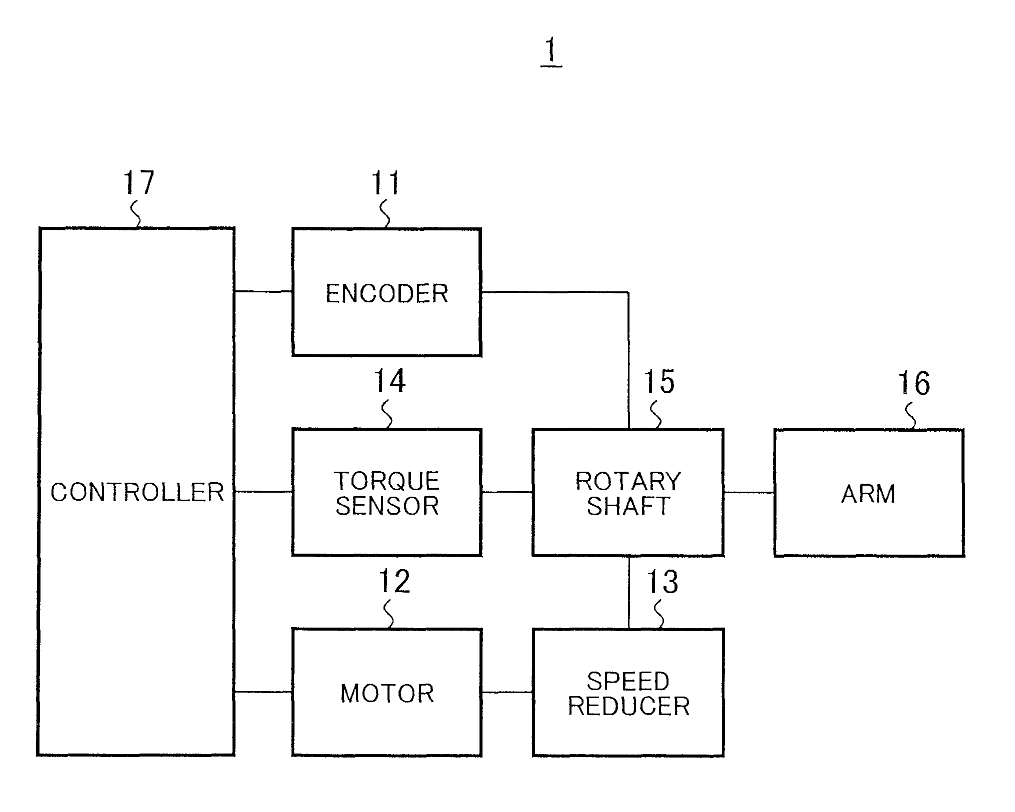
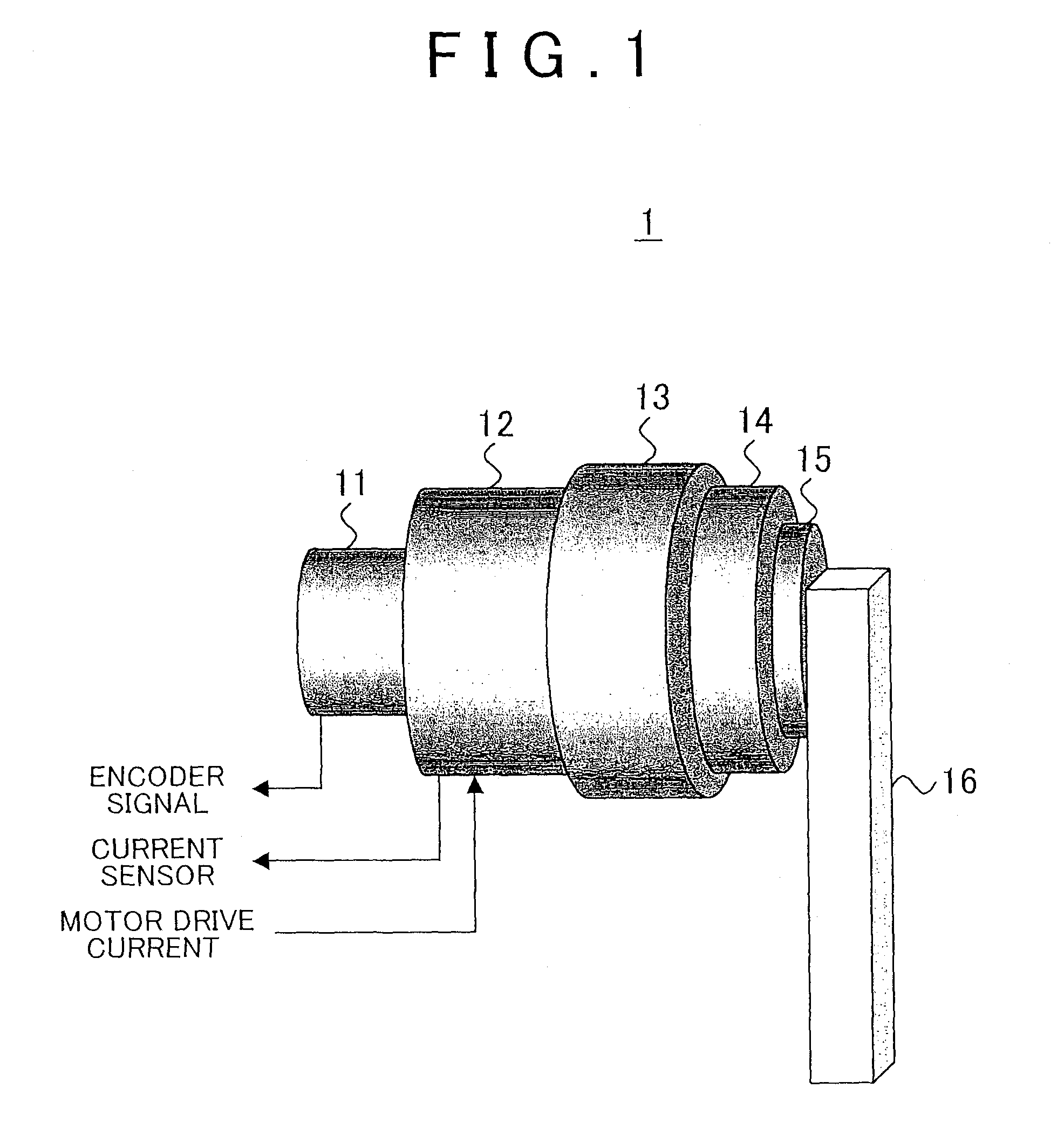
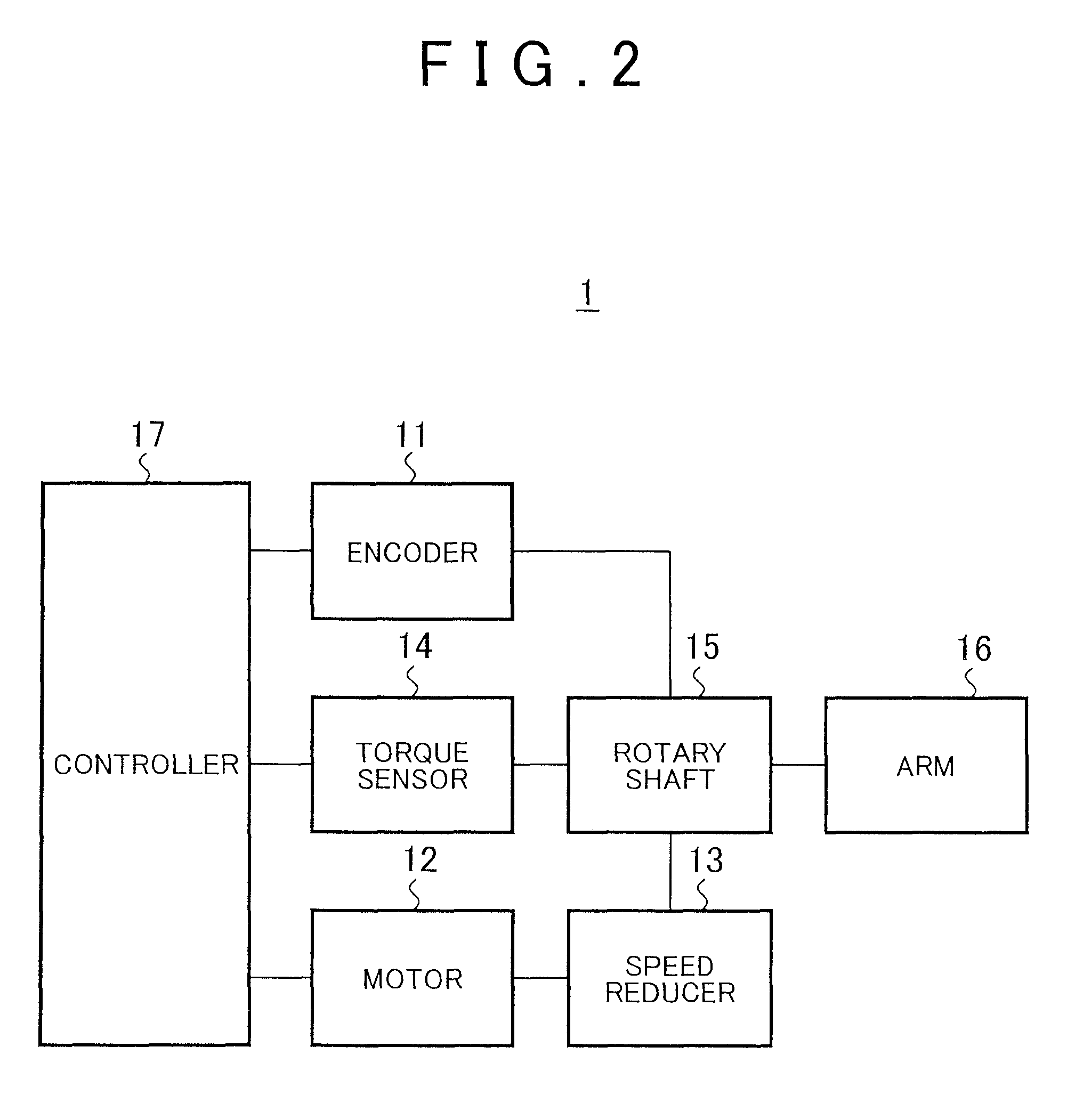
[0023]One embodiment of the invention will be described with reference to the drawings. FIG. 1 schematically illustrates the construction of an arm device 1 according to the embodiment. FIG. 2 is a block diagram of the arm device 1. The arm device 1 includes an encoder 11, a motor 12, a speed reducer 13, a torque sensor 14, a rotary shaft 15, an arm 16, and a controller 17. As shown in FIG. 1, the arm device 1 is a single-axis arm. In this embodiment, a gravity compensating method of a single-axis control system will be described.

[0024]The encoder 11 (corresponding to the above-mentioned position detector) detects the angle (position), amount of rotation, angular velocity, etc. of the rotary shaft 15. The encoder 11 outputs an encoder signal representing the detected angle, amount of rotation, angular velocity, etc., to the controller 17. In this manner, the angle of the arm 16, for example, is detected.

[0025]The motor 12 receives motor drive current generated from the controller 17...


PUM

PropertyMeasurementUnit
rotational angleaaaaaaaaaa

Abstract

According to a torque detecting method, gravitational torque applied to a rotary shaft of an arm is detected in a condition where position control of the arm is stopped, when the arm is located at a first position at which the arm is oriented in a direction different from a direction of gravitational force. Then, a gravity coefficient used for calculating gravitational torque corresponding to a position of the arm is calculated, based on the gravitational torque and the first position. Then, gravitational torque during position control is calculated, based on the position of the arm detected during the position control, and the gravity coefficient. Further, an actual output torque during the position control is calculated, based on operating torque applied to the rotary shaft and detected during the position control, and the gravitational torque calculated during the position control.

Description

CROSS-REFERENCE TO RELATED APPLICATIONS[0001]This is a national phase application based on the PCT International Patent Application No. PCT / IB2013 / 000638 filed Mar. 18, 2013, which claims priority to Japanese Patent Application No. JP 2012-064319, filed on Mar. 21, 2012, the entire contents of which are incorporated herein by reference.BACKGROUND OF THE INVENTION[0002]1. Field of the Invention[0003]The invention relates to a torque detecting method and an arm device.[0004]2. Description of Related Art[0005]When servo control is performed on a single-axis arm, using force (torque) detected with a torque sensor, compensation needs to be made in view of the effect of self-weight torque, mechanical deviation arising upon mounting of the torque sensor, frictional force produced during rotation of the arm, and so forth.[0006]A gravity compensation method of a control system that performs force control is disclosed in Japanese Patent Application Publication No. 62-60010 (JP 62-60010 A). Ac...

Claims


Application Information

Patent Timeline
Patent Type & Authority Patents(United States)
IPC IPC(8): G05B15/00G05B19/00G01L25/00B25J9/16G01L5/22
CPCB25J9/1633B25J9/16B25J9/1692G01L5/226G01L25/003
Inventor KOSAKA, YUSUKEOKAMOTO, KUNIHIRO
Owner TOYOTA JIDOSHA KK
Why Eureka
Try Eureka