LED module

a technology of led modules and led modules, applied in the field of light-emitting diodes, can solve the problems of many led modules, difficult work of thermal epoxies, and decreased brightness and expected life of led modules, and achieve the effect of promoting rapid and efficient heat transfer

Active Publication Date: 2017-01-03
MAG INSTR INC
View PDF2 Cites 55 Cited by
  • Summary
  • Abstract
  • Description
  • Claims
  • Application Information

AI Technical Summary

Benefits of technology

[0010]To the above end, in a preferred embodiment, the LED module is provided comprising an LED, a first circuit board, a lower assembly formed by a lower contact and a lower insulator, a second circuit board, an upper assembly formed by an upper insulator and upper contacts, and a heat sink formed by an outer housing and a contact ring. The LED and the heat sink are affixed to the first circuit board, preferably via a solder connection. The first circuit board, which has a plurality of thermally conductive layers connected by thermal vias, promotes the rapid and efficient transfer of heat from the LED to the heat sink.
[0011]In the preferred embodiment, the LED module also provides for a bond between the LED and the first circuit board, as well as bond between the first circuit board and the heat sink, that exhibit improved thermal, electrical, and mechanical characteristics, and that are less susceptible to premature failure.
[0012]In the preferred embodiment, the LED module also provides for protection against incorrect insertion or alignment of the power source that supplies energy to the LED, as well as improved mechanical stability and shock resistance to outside forces.
[0013]In the preferred embodiment, the LED module also provides for redundancy in the channels of electrical communication between components, thereby rendering the module less susceptible to failure from electrical interruptions.
[0014]In the preferred embodiment, the LED module also provides for an improved assembly that tolerates larger mechanical tolerances, that eliminates cure times, and that has increased flexibility in the orientation of its constituent components.

Problems solved by technology

However, the brightness and expected life of an LED typically decreases with increased temperature.
Further, a limitation on many LED modules is the medium used to affix the LED to its supporting substrate.
Thermal epoxies are difficult to work with and require extended cure times. LED attachments using thermal epoxies also have an increased incidence of premature failure.
Another limitation on many LED modules, especially those intended for use in flashlights and other portable lighting devices, is their inability to prevent operation of the lighting device when the power source (e.g., one or more batteries) are incorrectly aligned.
A further limitation on known LED modules, such as described in U.S. Patent Publication 2007 / 0058366 A1 (published Mar. 15, 2007), has been their relative complexity of assembly or manufacture.
Finally, another limitation on many LED modules used in portable lighting devices is their susceptibility to failure caused by electrical interruptions and / or shock from outside forces.

Method used


Image

  • LED module
  • LED module
  • LED module

Examples


Embodiment Construction

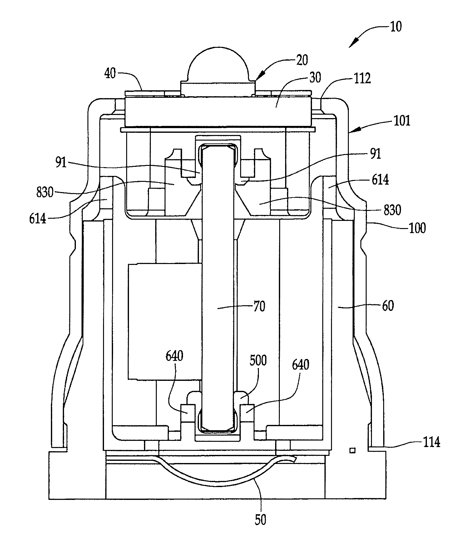
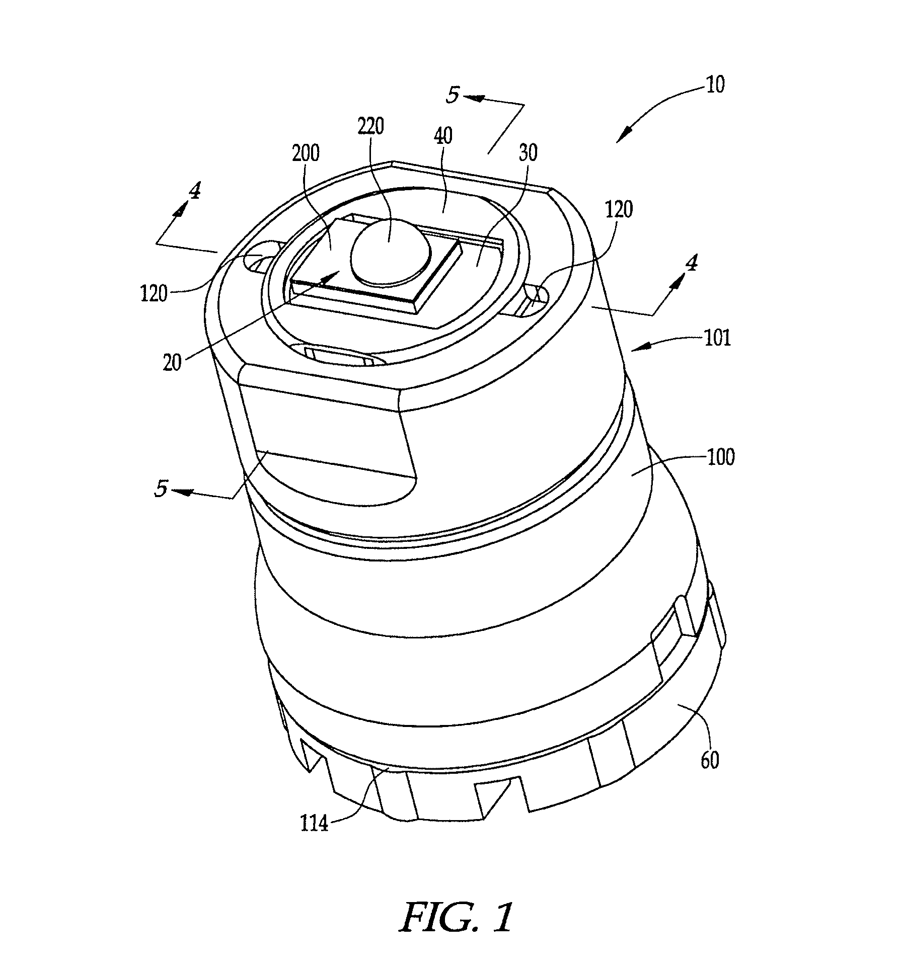
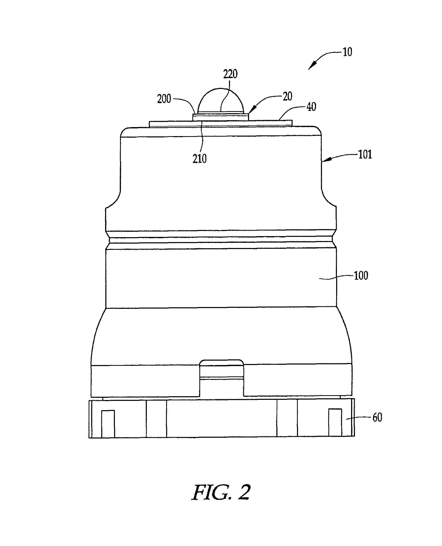
[0036]An LED module 10, according to a preferred embodiment, is shown in FIGS. 1-5. In the illustrated embodiment, the LED module 10 includes an LED 20, a first circuit board 30, a lower assembly 55 formed by a lower contact 50 and a lower insulator 60, a second circuit board 70, an upper assembly 85 formed by an upper insulator 80 and upper contacts 90, 91, and a heat sink 101 formed by an outer housing 100, preferably made of metal, and a contact ring 40.

[0037]The LED 20 can be any light emitting diode that can be soldered to a printed circuit board. Preferably the LED 20 can be soldered to the first circuit board 30 using a screen applied solder paste and a reflow oven. More preferably, the LED 20 is the LUXEON® Rebel product commercially available from Philips Lumileds Lighting Company, LLC. The LED 20 has an upper surface 200 and a lower surface 210. The upper surface 200 has a diode 220 that is capable of emitting visible light in a direction away from the upper surface 200. T...


PUM


Abstract

A light emitting diode (“LED”) module with improved thermal characteristics is provided. The module includes an LED, a first circuit board, a second circuit board, a lower insulator, an upper insulator, a lower contact, upper contacts, and a heat sink. Preferably, the heat sink comprises an outer housing and a contact ring. The LED and the heat sink are attached to the first circuit board via solder. In addition to serving as a substrate for the LED, the first circuit board (which contains a plurality of thermally conductive layers connected by vias) facilitates the transfer of heat away from the LED to the heat sink. The module also has improved mechanical and electrical properties, including redundant electrical connections, stable mechanical connections, and a shock-absorbing lower contact. The lower insulator can also be configured to prevent misalignment of the power source with the lower contact when the module is used in a flashlight or other lighting device.

Description

CROSS-REFERENCE TO RELATED APPLICATION[0001]The application is a continuation of application Ser. No. 12 / 188,201, filed Aug. 7, 2008, now U.S. Pat. No. 9,022,612, issued May 5, 2015, the contents of which are incorporated by reference as if fully set forth herein.FIELD OF THE INVENTION[0002]The field of the present invention relates to a light emitting diode (“LED”) module, and pertains particularly to an LED module for use in hand-held and other portable lighting devices, such as flashlights and headlamps.BACKGROUND OF THE INVENTION[0003]LEDs have been used in various applications, including illuminating watches, transmitting information from remote controls, and forming images on jumbo television screens. More recently, LEDs have been used in portable lighting devices (such as flashlights and headlamps) because, among other things, LEDs can last longer, produce light more efficiently, and be more durable than incandescent lamps commonly used in conventional flashlights and headlam...

Claims


Application Information

Patent Timeline
Patent Type & Authority Patents(United States)
IPC IPC(8): F21L4/02F21K99/00F21V15/04F21V23/04F21V29/00F21V23/00F21V29/507F21V29/74F21V29/89F21V29/508F21V29/70H05K1/02H05K3/42F21W101/10F21W111/10F21Y101/00
CPCF21L4/027F21K9/00F21V15/04F21V23/005F21V23/006F21V23/04F21V29/004F21V29/507F21V29/508F21V29/70F21V29/74F21V29/89H05K1/0207F21W2101/10F21W2111/10F21Y2101/00H05K1/0206H05K3/429H05K2201/09309H05K2201/09518H05K2201/10106F21Y2115/10F21V19/005F21V23/0414F21V23/06F21W2102/00
Inventor MAGLICA, ANTHONYWEST, STACEY H.RADLOFF, ROBERT P.
Owner MAG INSTR INC
Why Eureka
Try Eureka