
Refrigerator and control method thereof

a technology of refrigerators and control methods, applied in the field of refrigerators, can solve the problems of increased construction costs, increased maintenance costs, and increased power consumption, and achieve the effect of preventing concentration of power consumption

Active Publication Date: 2017-01-03
SAMSUNG ELECTRONICS CO LTD
View PDF12 Cites 11 Cited by
  • Summary
  • Abstract
  • Description
  • Claims
  • Application Information

AI Technical Summary

Benefits of technology

[0013]Therefore, it is an aspect of the present disclosure to provide a refrigerator that controls an operation rate or operation time of at least one load at a time zone at which power consumption is concentrated, thereby preventing concentration of power consumption, and a control method thereof.
[0014]It is another aspect of the present disclosure to provide a refrigerator that raises target temperature of a storage compartment at a time zone at which power consumption is concentrated, thereby reducing power consumption, and a control method thereof.
[0020]When the power-saving signal is the first power-saving mode, the control device may raise target temperature of the storage compartment by a predetermined temperature and reset the target temperature, and may control the operation of the compressor, the valve, and the fan so that the temperature of the storage compartment is maintained at the reset target temperature.
[0024]The refrigerator may further include an ice-making compartment, a tray provided in the ice-making compartment to make ice, a water supply valve to adjust supply of water to the tray, an ice-making evaporator to cool the tray, an ice-making valve to adjust flow of a refrigerant supplied to the ice-making evaporator, and an ice-separating heater to separate the ice from the tray, wherein, when the power-saving signal is the second power-saving level of the first power-saving mode, the control device may determine whether it is ice-making operation time and, upon determining that it is the ice-making operation time, may lower an operation rate of the compressor.
[0026]When the power-saving signal is the third power-saving level of the first power-saving mode, the control device may determine whether an ice-making operation is being performed and, upon determining that the ice-making operation is being performed, may complete the ice-making operation and ice separation, and upon determining that it is a next ice-making operation time, may control the water supply valve, the ice-separating heater, and the ice-making valve to be off until first execution time elapses to delay the next ice-making operation.
[0033]The executing the first power-saving mode may include determining a power-saving level of the first power-saving mode, when the determined power-saving level is a second power-saving level, controlling the compressor, the fan, and the valve so that the temperature of the storage compartment is maintained at the reset temperature, determining whether it is ice-making operation time of an ice-making unit provided in the storage compartment, and, upon determining that it is the ice-making operation time, lowering an operation rate of the compressor.

Problems solved by technology

Although the refrigerator provides user convenience, the refrigerator consumes a large amount of power due to increased capacity and various functions thereof, which makes the cost burden too heavy for users in connection with the increase of electric charges.
However, such additional construction of power plants may not be desirable in view of construction costs, maintenance costs, and environmental problems.
In the case of a refrigerator, if the refrigerator controls the specific function to be on or off based on the power price, the refrigerator may not efficiently perform a function desired by a user or may not perform a function related to performance improvement with the result that the performance of the refrigerator may be lowered.

Method used


Image

  • Refrigerator and control method thereof
  • Refrigerator and control method thereof
  • Refrigerator and control method thereof

Examples


Embodiment Construction

[0045]Reference will now be made in detail to the embodiments of the present disclosure, examples of which are illustrated in the accompanying drawings, wherein like reference numerals refer to like elements throughout.

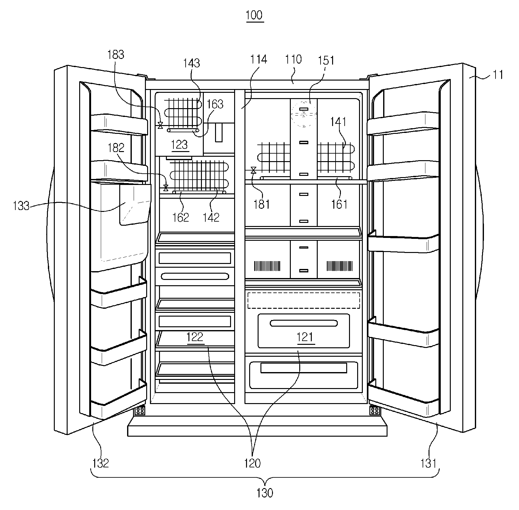
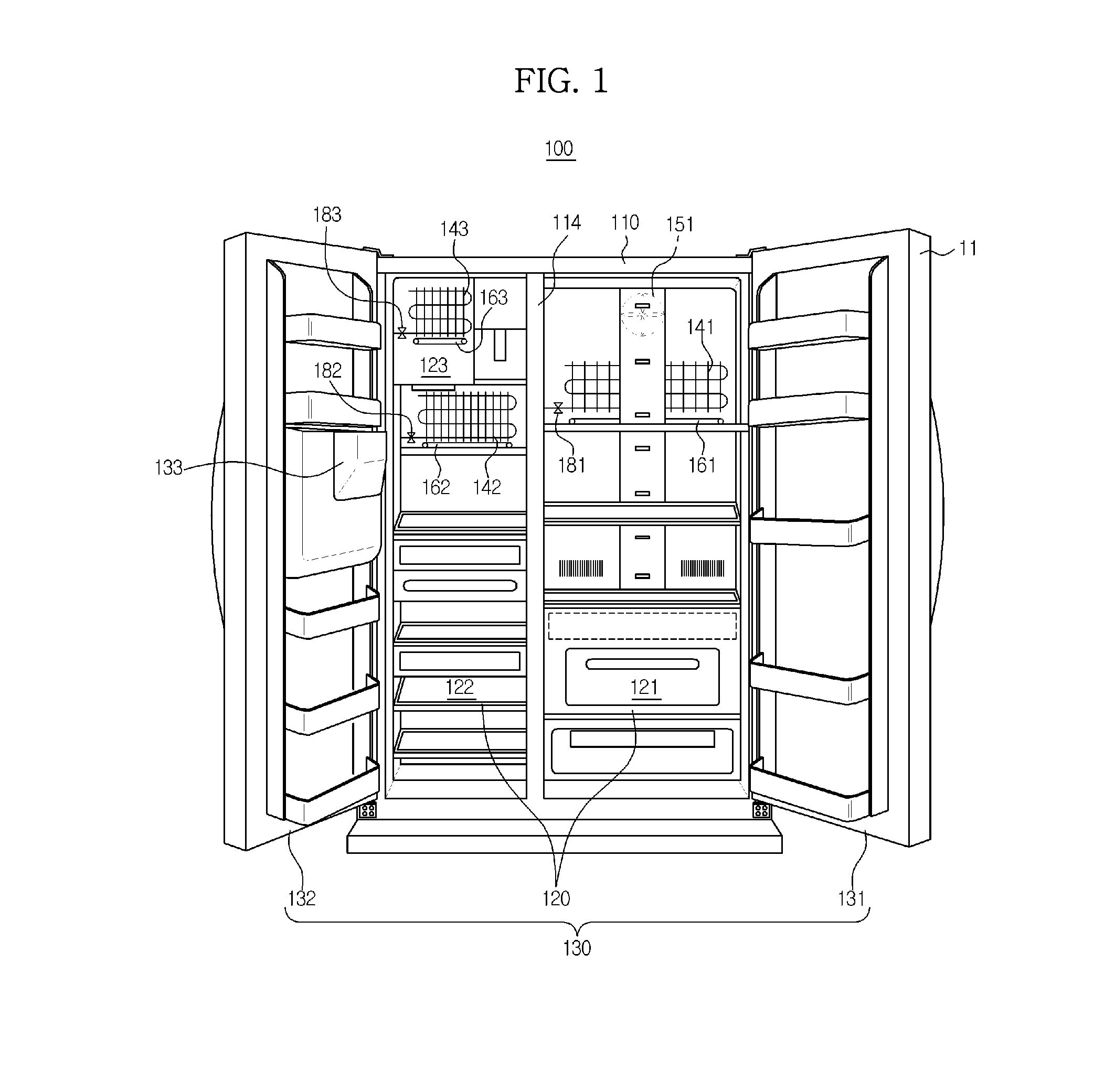
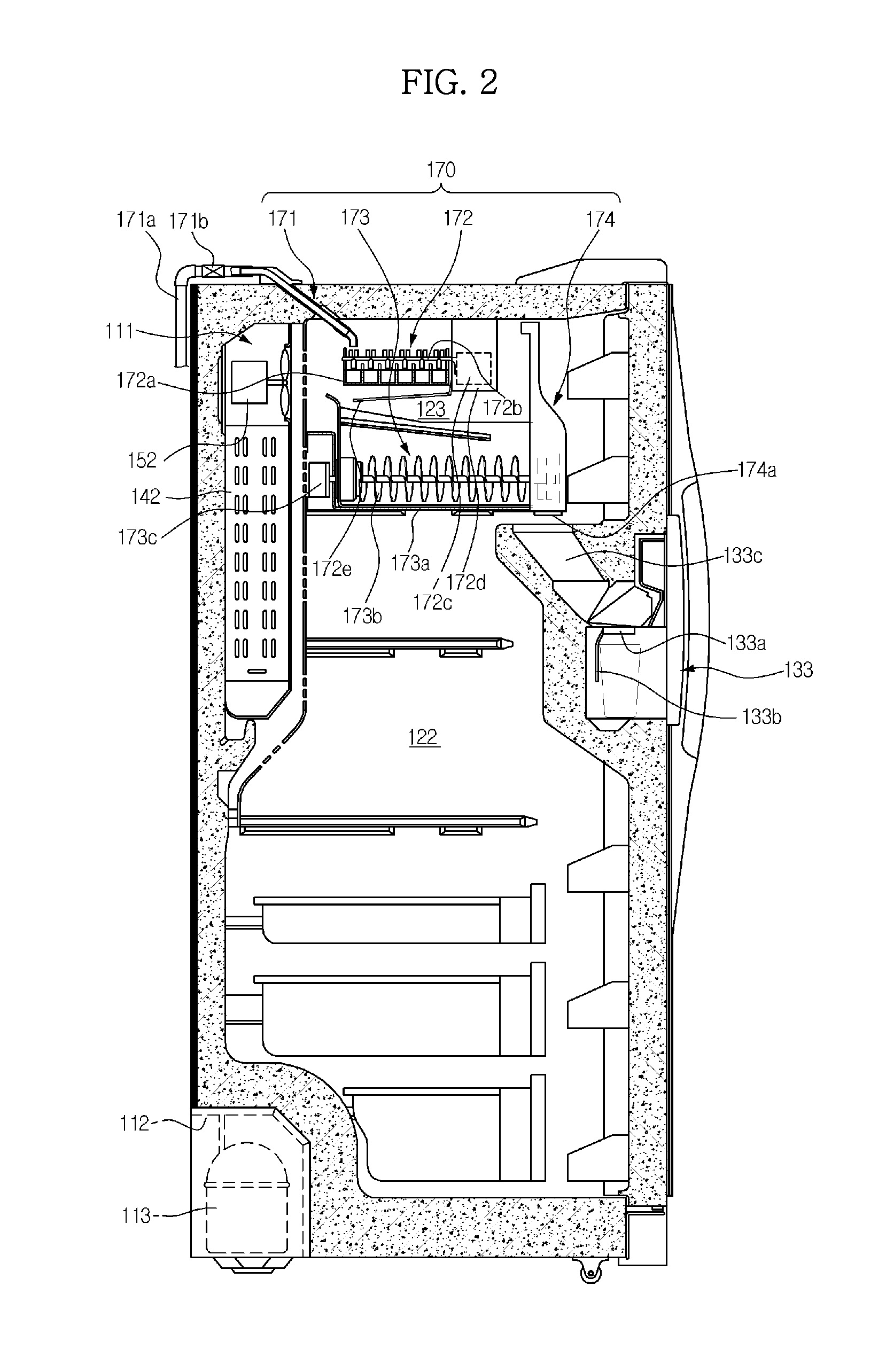
[0046]FIG. 1 is a perspective view of a refrigerator according to an embodiment of the present disclosure, and FIG. 2 is a view illustrating the interior of the refrigerator according to the embodiment of the present disclosure.

[0047]As shown in FIG. 1, a refrigerator 100 includes a main body 110, storage compartments 120 (121 and 122), and doors 130 (131 and 132).

[0048]The main body 110 forms the external appearance of the refrigerator 100. A duct 111, along which air flows, and a machinery compartment 112 are formed in an inner space of the main body 110.

[0049]In the machinery compartment 112 are mounted a compressor 113 to compress a refrigerant so that the refrigerant is discharged in a high-temperature and high-pressure state, a condenser (not shown) to condense ...


PUM


Abstract

A control method of a refrigerator including a compressor to supply refrigerant to an evaporator to cool a storage compartment, a valve to adjust flow of the refrigerant, a fan to blow air heat-exchanged by the evaporator, and a heater to remove frost from the evaporator. The control method includes, upon receiving a power-saving signal, determining whether the received power-saving signal is a first or second power-saving mode signal, upon determining that the power-saving signal is the first power-saving mode signal, performing at least one selected from among resetting of target temperature of the storage compartment, adjustment of an operation rate of the compressor, and adjustment of operation time of the heater to execute a first power-saving mode, and, upon determining that the power-saving signal is the second power-saving mode signal, controlling the compressor, the fan, and the heater to be off to execute a second power-saving mode.

Description

CROSS-REFERENCE TO RELATED APPLICATIONS[0001]This application claims the benefit of Korean Patent Application No. 2011-075697, filed on Jul. 29, 2011 in the Korean Intellectual Property Office, the disclosure of which is incorporated herein by reference.BACKGROUND[0002]1. Field[0003]Embodiments of the present disclosure relate to a refrigerator that controls driving of a load to reduce power consumption and / or electric charges and a control method thereof.[0004]2. Description of the Related Art[0005]A refrigerator is an appliance that keeps food and drinks fresh for a long period of time. The refrigerator stores food and drinks in a frozen state or in a refrigerated state depending upon kinds of the food and drinks.[0006]The refrigerator repeatedly performs a refrigeration cycle including compression, condensation, expansion, and evaporation through a compressor, condenser, expansion valve, and evaporator mounted in the refrigerator, and maintains the temperature of a storage compar...

Claims


Application Information

Patent Timeline
Patent Type & Authority Patents(United States)
IPC IPC(8): F25D17/00F25C5/08F25D29/00F25B49/02G05D23/32F25D17/04F25D21/00
CPCF25B49/022F25C5/08F25D29/00F25C2600/02F25D21/006F25D2700/12F25D2700/122Y02P60/855Y02P60/85F25D11/00F25D21/06F25D23/00
Inventor YOON, SINN BONGCHANG, EUI YOUNGCHOI, JONG CHULKIM, YONG HANLEE, WON JESI, JONG EON
Owner SAMSUNG ELECTRONICS CO LTD
Learn More