
Method and device for image-based visibility range estimation

a technology of visibility range and estimation method, applied in image enhancement, image data processing, instruments, etc., can solve problems such as visibility limitations, and achieve the effect of rapid and efficien

Active Publication Date: 2017-01-03
ROBERT BOSCH GMBH
View PDF4 Cites 0 Cited by
  • Summary
  • Abstract
  • Description
  • Claims
  • Application Information

AI Technical Summary

Benefits of technology

[0019]In the step of determining, extinction coefficient K may be determined using a one-dimensional equation. Extinction coefficient K may be determined using a model for light transmission by atmospheric aerosols. Advantageously, a one-dimensional equation and additionally or alternatively a model of horizontal view may enable a more rapid determination of extinction coefficient K. The model of horizontal view may be formulated as a one-dimensional equation.
[0020]In the step of determining, extinction coefficient K may be determined using an estimation method from the one-dimensional equation. This makes it possible to approximately and very rapidly determine extinction coefficient K. The estimation method may be carried out iteratively and approach determined extinction coefficient K to critical extinction coefficient K of an objective functional with each iteration.
[0026]The approach presented here also provides a device which is designed for carrying out, controlling, or implementing the steps of one variant of a method provided here in appropriate devices. The object on which the present invention is based may also be achieved rapidly and efficiently by this embodiment variant of the present invention in the form of a device.

Problems solved by technology

For cameras having a spectral range approximately in the area of the visible light, mainly fog may in this way result in visibility limitations.

Method used


Image

  • Method and device for image-based visibility range estimation
  • Method and device for image-based visibility range estimation
  • Method and device for image-based visibility range estimation

Examples


Embodiment Construction

[0041]In the following description of advantageous exemplary embodiments of the present invention, identical or similar reference numerals are used for elements which are similar operating elements and represented in the various figures, a repeated description of these elements being omitted.

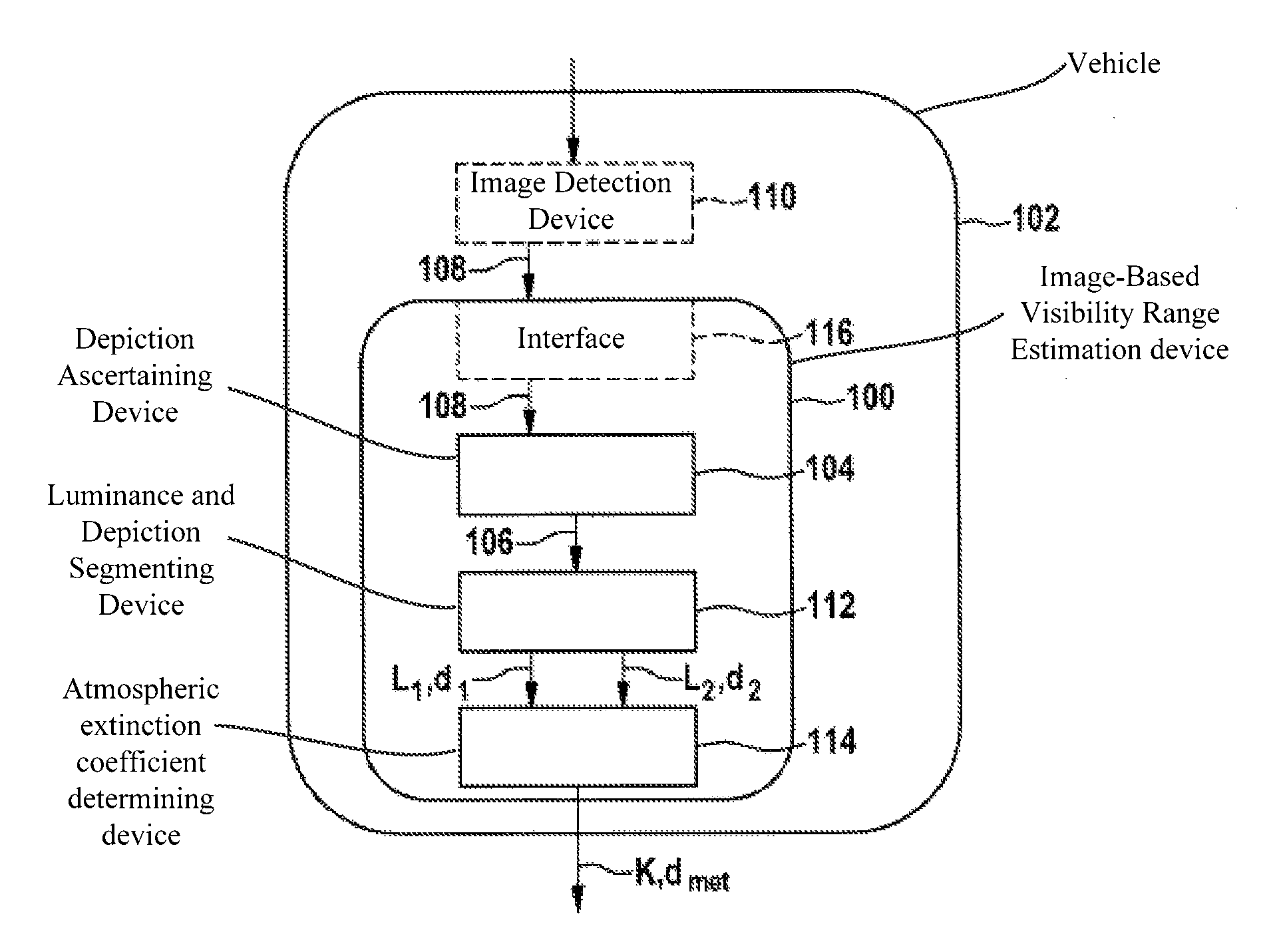
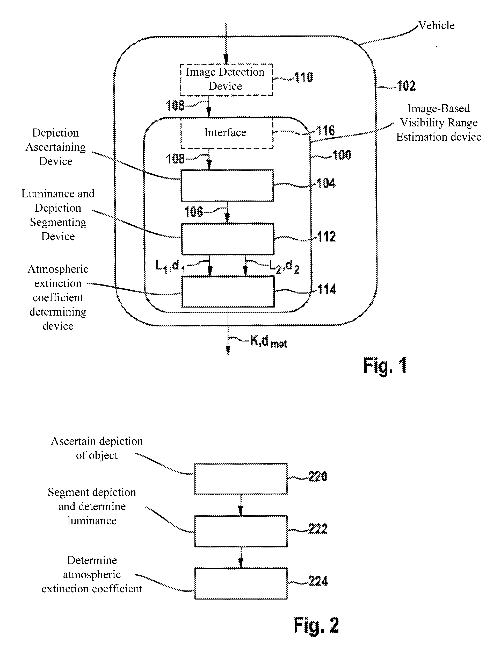
[0042]FIG. 1 shows a block diagram of a device 100 for the image-based visibility range estimation for a vehicle 102 according to one exemplary embodiment of the present invention. Device 100 includes a device 104 for ascertaining a depiction 106 of an object of the surroundings in an image 108 of an image detection device 110 of vehicle 102, and a device 112 for segmenting a first object range of the object having an equal first distance d1 within a tolerance range to image detection device 110 and a second object range of the object having an equal second distance d2 within a tolerance range to image detection device 110. Device 112 is furthermore designed to determine a first object luminance...


PUM

PropertyMeasurementUnit
thresholdaaaaaaaaaa
distanceaaaaaaaaaa
distanceaaaaaaaaaa

Abstract

A method for image-based visibility range estimation for a vehicle includes: ascertaining a depiction of an object of the surroundings in an image of an image detection device of the vehicle, the object having an extension in the direction of travel of the vehicle, the image showing a depiction of surroundings ahead of the vehicle; segmenting the depiction of the object in order to obtain first and second object ranges of the object having respective first and second distances to the image detection device within respective tolerance ranges; determining a first object luminance of the first object range and a second object luminance of the second object range; and determining an atmospheric extinction coefficient correlated to the visibility range, using the first and second object luminances, and the first and second distances.

Description

CROSS-REFERENCE TO RELATED APPLICATION[0001]This application claims foreign priority benefits under 35 U.S.C. §119 to German Application No. 10 2014 208 271.4, filed on May 2, 2014.BACKGROUND OF THE INVENTION[0002]1. Field of the Invention[0003]The present invention relates to a method for an image-based visibility range estimation, to a corresponding device for the image-based visibility range estimation, as well as to a corresponding computer program product.[0004]2. Description of the Related Art[0005]With a rapid further development of sensors and systems, an increasingly accurate detection of the vehicle surroundings is made possible. Different driver assistance systems may thus support the human driver in his or her driving task and / or assume parts of the tasks completely. Various active and passive sensors work with the aid of different electromagnetic spectral ranges. Depending on the spectral range, more or less strong dampening and scattering effects may occur due to atmos...

Claims


Application Information

Patent Timeline
Patent Type & Authority Patents(United States)
IPC IPC(8): G06K9/00G06K9/46G01N21/53G08G1/16B60W40/02G06T7/00
CPCG06K9/4661B60W40/02G01N21/538G06K9/00791G06T7/00G06T7/0051G06T7/0079G06T7/0081G08G1/16G06T2207/10016G06T2207/10021G06T2207/10028G06T2207/30252G06T2207/30256G06T7/50G06T7/11G06T7/10G06V20/56
Inventor LENOR, STEPHEN
Owner ROBERT BOSCH GMBH
Learn More