
Speaker device

a technology of speaker device and speaker, which is applied in the direction of transducer details, electrical transducers, electrical apparatus, etc., can solve the problems that the current situation is hardly addressed comprehensively and fundamentally, and achieve the effects of reducing vibration, increasing damage, and promoting effects

Active Publication Date: 2017-01-03
NAGAOKA MITSUO
View PDF15 Cites 2 Cited by
  • Summary
  • Abstract
  • Description
  • Claims
  • Application Information

AI Technical Summary

Benefits of technology

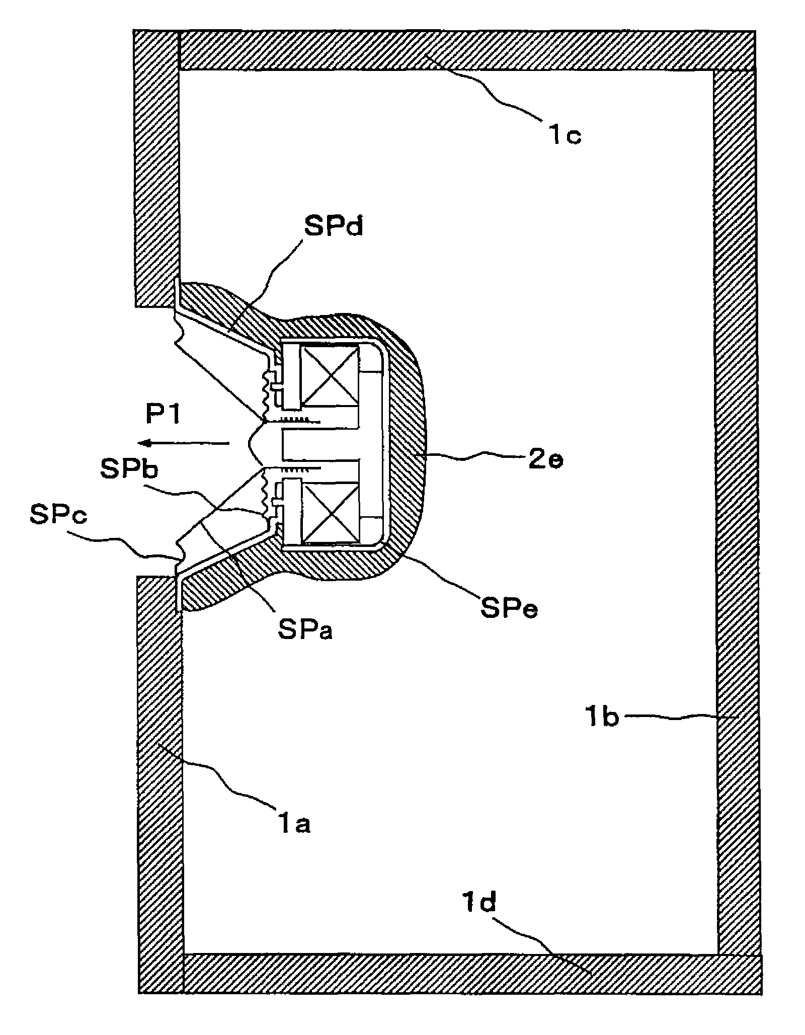
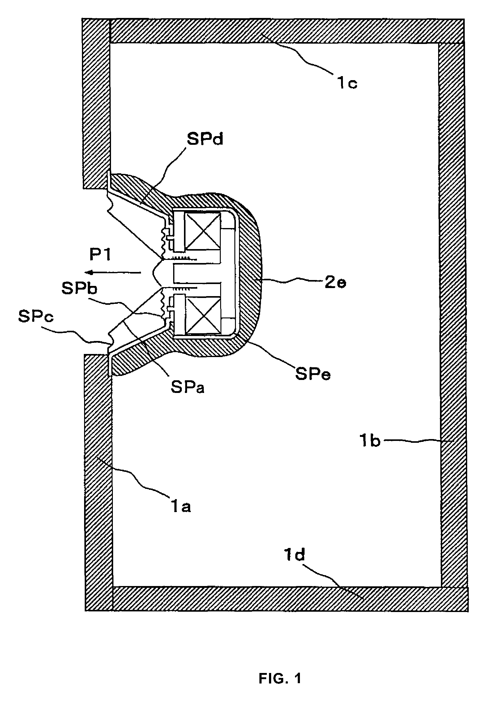
[0043]In the invention (1), the formation of the viscoelastic material layer including also the internal loss of the viscoelastic material is large, and converted to thermal energy and vibration energy, there is no resonance itself, it becomes strengthening of stiffness and damping material layer formation relative to the loudspeaker unit frame, and for the strong vibration of the loudspeaker frame caused by the edge, the damper, the magnet simultaneously with the vibration of the vibrating cone of the loudspeaker unit, these suppress the vibration and hasten the decay of the vibration. In FIG. 24, the movement to the front of the vibrating cone of the loudspeaker unit and the movement to the back of the magnet occurs at the same time, it becomes that it pulls down the front and back of the loudspeaker unit frame, so the frame vibration but begins, but the damping is exhibited formation of the viscoelastic material layer is a layer formed of the non-restraint damping material layer, because of an originating point of vibration concave portion of the frame, here is a form close to the formation of the restraint damping material layer, damping is increased. The frame part of the loudspeaker unit is in contact with cabinet, moreover, it is a part that is in contact with the vibrating cone through the edge and damper, since the vibration here has had a strong impact on the turbidity of the sound, the reducing the vibration of here is the most fundamental, if you go the other measures do not sufficiently suppressed, it is to leave a distortion not be taken, therefore this is the most important part. Although want to the formation of the viscoelastic layer on the back side of the loudspeaker frame, it's so difficult to the formation the location of the loudspeaker units, so an application impossible region, but applied in the manufacturing process of the loudspeaker unit, doing so formed further promote effects. Further, the viscoelastic material because it has too stiff with increasing thickness of the layer, due to reducing the frame vibration of the loudspeaker unit, so the early decay and decline of the surplus vibration becomes realization of the sound with less distortion, then it becomes for the vibrating cone of the loudspeaker unit, a fine reproduction of the sound which has been masked by the frame vibration, it becomes the improvement of the resolution and it is improving the reality. The evaluation of sound quality is the most severe evaluated by listening sense, with comprehensive and depth localization and sound and tone, the comparison with real acoustic instruments, is evaluated to detect subtle differences.
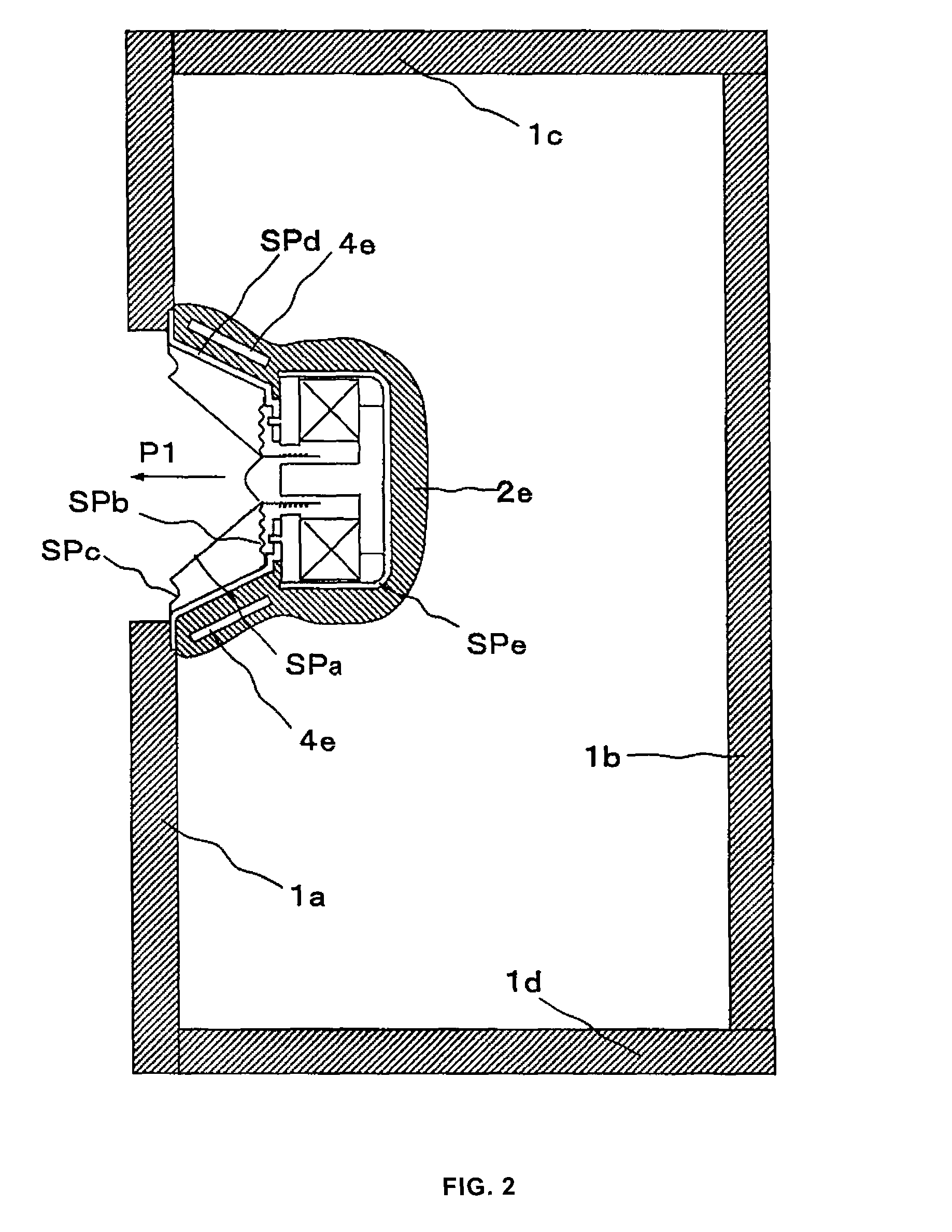
[0044]In the invention (2), the vibrating cone vibration and the vibration of the magnet due to the reaction with the vibrating cone vibration are strong, about all surfaces of the rear surface of the loudspeaker units such as the frame back surface of the loudspeaker unit since a thickness of more than 10 mm due to the formation of the viscoelastic material layer, by having an auxiliary member having rigidity among the layers, between the auxiliary member and the frame of the speaker unit, it becomes damping layer in the form close to the restraint type from the non-restraint type up to it, as well as increase the effect of damping, the auxiliary member loudspeaker frame of the second, it also serves as a frame with reduced vibration, to get sound with less distortion due to a decrease in this frame vibration.
[0045]In the invention (3), by the presence of sand or coarse-grain object like sand, the damping described above is accomplished more effectively, therefore it is possible to further enhance the effect of the present invention.
[0046]In the invention (4), the formation of the viscoelastic material layer including also the internal loss of the viscoelastic material is large, and converted to thermal energy and vibration energy, there is no resonance itself, it becomes strengthening of stiffness and damping material layer formation relative to the vibration of the baffle of the loudspeaker mount periphery caused by the loudspeaker unit, and these suppress the vibration and hasten the decay of the vibration. Therefore the early decay and decline of the surplus vibration becomes realization of the sound with less distortion, then it becomes for the vibrating cone of the loudspeaker unit, a fine reproduction of the sound which has been masked, it becomes the improvement of the resolution and it is improving the reality.
[0047]In the invention (5), the loudspeaker unit vibration and the baffle vibration about of the loudspeaker unit mounting area around are strong, about the baffle inside surfaces to the baffle vibration of the loudspeaker unit mounting area, since a thickness of more than 10 mm due to the formation of the damping material layer, by having an auxiliary member having rigidity among the layers, between the auxiliary member and the frame of the speaker unit, it becomes damping layer in the form close to the restraint type from the non-restraint type up to it, as well as increase the effect of damping, the auxiliary member as the second baffle, it also serves as a frame with reduced vibration, to get sound with less distortion due to a decrease in this vibration.
[0048]In the invention (6), by the presence of sand or coarse-grain object like sand, the damping described above is accomplished more effectively, therefore it is possible to further enhance the effect of the present invention.

Problems solved by technology

However, the loudspeaker unit of the loudspeaker system is a vibration generator, sound emission by the vibration of the loudspeaker vibrating cone is a purpose, and the loudspeaker frame and the all panels of the cabinet should be a stationary point of the non-vibrating, but the vibrating cone unit vibrates vibration accompanying occurs with adverse effect these vibrations are superimposed on the generated sound from the vibrating member of the loudspeaker unit direct sound emission from a cabinet is also made.
However, in a schematic diagram of the process of propagation of the vibration shown in FIG. 24, for the deformation of each place and vibration propagation emanating from the loudspeaker unit that occur at the same time sound comes out at the start of the first vibration, the current situation is hardly addressed comprehensively and fundamentally.
Thus, if two of three adverse effects are manufactured enough in consideration of rigidity and a vibration suppression, it will go towards solution, however, in this arrangement, it has not been solved about the vibration P6 by the side of the loudspeaker magnet by the action and reaction of vibration of the vibrating cone of a loudspeaker unit, and also since two loudspeaker units operate in the same direction for the same volume, the action and reaction vibration P6 increases.

Method used


Image

  • Speaker device
  • Speaker device
  • Speaker device

Examples


embodiment 1

[0103]FIG. 1 is a representation of the cross-sectional structure of a loudspeaker system according to the embodiment 1 of the present invention. The embodiment 1 is a loudspeaker system characterized in the viscoelastic material layer formed by viscoelasticity sealing material of denaturation silicone or polyurethane, or viscoelastic adhesive of denaturation epoxy, denaturation silicone epoxy, urethane or any mixture thereof, with the thickness of 1 mm or more in the region of more than 70% of the total area of the loudspeaker frame back side surface and the magnet back side surface except for the part required for installation and moving parts such as edge, damper and vibrating cone of the loudspeaker unit. That the internal loss of the viscoelastic material is large, there is no resonance of itself becomes a realization of the sound with less distortion, it becomes for the vibrating cone of the loudspeaker unit, a fine reproduction of the sound which has been masked, it becomes t...

embodiment 2

[0108]FIG. 2 is a representation of the cross-sectional structure of a loudspeaker system according to the embodiment 2 of the present invention. The embodiment 2, it is a loudspeaker system of FIG. 1 having an auxiliary member having rigidity within the viscoelastic material layer of the loudspeaker frame, the vibration of the magnet due to the reaction with the vibrating cone vibration is strong, therefore the damping due to the formation of the viscoelastic material layer to the surface of all of the backside of the speaker units such as the frame surface of the speaker unit backside because a thickness exceeding 10 mm, having an auxiliary member having a rigidity among the layers becomes as close to the restraint vibration suppression, it increases the effect of damping, to obtain a sound with little distortion. Auxiliary member with this rigidity is the iron plate or 3 mm thickness, 10 mm width, 30 mm length, or metal such as bolts about the same length, wood material or plasti...

embodiment 3

[0109]FIG. 3 is a representation of the cross-sectional structure of a loudspeaker system according to the embodiment 3 of the present invention. The embodiment 3 is the loudspeaker system of FIG. 1 with that the viscoelastic material layer 2f made of the viscoelasticity sealing material of denaturation silicone or polyurethane, or viscoelastic adhesive of denaturation epoxy, denaturation silicone epoxy, urethane or any mixture thereof, is formed with a thickness of 2 mm or more with the entire annular larger 40 mm more than the loudspeaker unit mounting portion of the loudspeaker unit on the mounting baffle inside surface. This is to form the annular viscoelastic material layer 2f to vicinity of the loudspeaker unit mounting portion the inside surface of the cabinet of FIG. 3, and this is due to the internal loss of the viscoelastic material, in addition to the suppression of vibration of the loudspeaker unit, the vibration of the peripheral baffle mounting portion of the loudspeak...


PUM

PropertyMeasurementUnit
thicknessaaaaaaaaaa
thicknessaaaaaaaaaa
thicknessaaaaaaaaaa

Abstract

The object of the present invention is that the surplus vibration involved therewith simultaneously generating a sound wave by the vibration of the vibrating cone of the loudspeaker unit is generated in the loudspeaker system, which has impaired the sound quality of the loudspeaker system. The purpose of the present invention is to provide a technique for improving the sound quality by reducing the this surplus vibration which are the loudspeaker frame vibration and the cabinet vibration like a front baffle vibration. The present invention is characterized in being configured with a viscoelastic material layer upon rear portions such as the frame surface of the loudspeaker unit and inside and outside surfaces of each surface configuring the loudspeaker cabinet, and additionally suppresses vibration by addition of a heavy member or pressurization caused by constraint of a binding member.

Description

TECHNICAL FIELD[0001]This application, which claims priority based on Japanese Patent Application JP 2011-36515 and Japanese Patent Application JP2011-36514 filed on Feb. 23, 2011 in Japan, the contents of which are incorporated herein by reference.[0002]The present invention relates to a loudspeaker system.BACKGROUND ART[0003]Common loudspeaker equipment is shown in FIG. 22 in full-range loudspeaker unit use and an enclosure formal cabinet, furthermore FIG. 23 shows generating of sound and the vibrational state of a loudspeaker unit and the vibrational state of the cabinet by vibration of the vibrating cone of a loudspeaker unit, and the direction of an arrow of the figure is shown in the state in case the vibrating cone operates ahead by plus polarity, and FIG. 24 shows the schematic drawing the vibration propagation process. The loudspeaker system is established by the vibrating cone anteroposterior vibration of the loudspeaker unit by Fleming's left-hand rule between the magneti...

Claims


Application Information

Patent Timeline
Patent Type & Authority Patents(United States)
IPC IPC(8): H04R11/00H04R1/02H04R9/06H04R1/28C09J9/00H04R7/16
CPCH04R1/02C09J9/00H04R1/288H04R1/2896H04R1/2819H04R1/2842H04R1/2857H04R7/16H04R2207/00H04R2231/00
Inventor NAGAOKA, MITSUO
Owner NAGAOKA MITSUO
Learn More