Noise attenuation panel and a gas turbine component comprising a noise attenuation panel

Active Publication Date: 2012-07-05
GKN AEROSPACE SWEDEN AB
View PDF9 Cites 21 Cited by
  • Summary
  • Abstract
  • Description
  • Claims
  • Application Information

AI Technical Summary

Benefits of technology

[0018]According to a further development of the last-mentioned embodiment, at least three cells of said at least three interconnected cells are arranged along a straight line. This design further creates conditions for achieving a minimized resonance frequency.
[0019]According to a further development of the last-mentioned embodiment, only the first cell in said at least three interconnected cells is provided with a through hole in its associated part of the first wall. This design further creates conditions for achieving a longer distance between the inlet hole (through hole in the first wall) to the first cell and an end wall in the last cell (the second cell) in the-series of interconnected cells.
[0020]According to a further preferred embodiment, one of said communication holes to the first cell is provided at the opposite end of the partition wall in relation to the first wall. This design further creates conditions for achieving a longer effective distance between the inlet hole (through hole in the first wall) to the first cell and an end wall in the last cell (the second cell) in the series of interconnected cells.
[0021]According to a further development of the last-mentioned embodiment, one of said communication holes is provided between the second cell and an intermediate cell between the first and second cells in the interconnected cells in the vicinity of the first wall. This design further creates conditions for achieving a longer dista

Problems solved by technology

The drawback of this type of liner is that the resonance frequency is determined, by the ratio between the cross-area/depth ratio of the neck and the volume of the body.
The noise is primarily generated between the fan and an arrangement of outlet guide vanes positioned downstream of the fan.
Fu

Method used


Image

  • Noise attenuation panel and a gas turbine component comprising a noise attenuation panel
  • Noise attenuation panel and a gas turbine component comprising a noise attenuation panel
  • Noise attenuation panel and a gas turbine component comprising a noise attenuation panel

Examples


Example

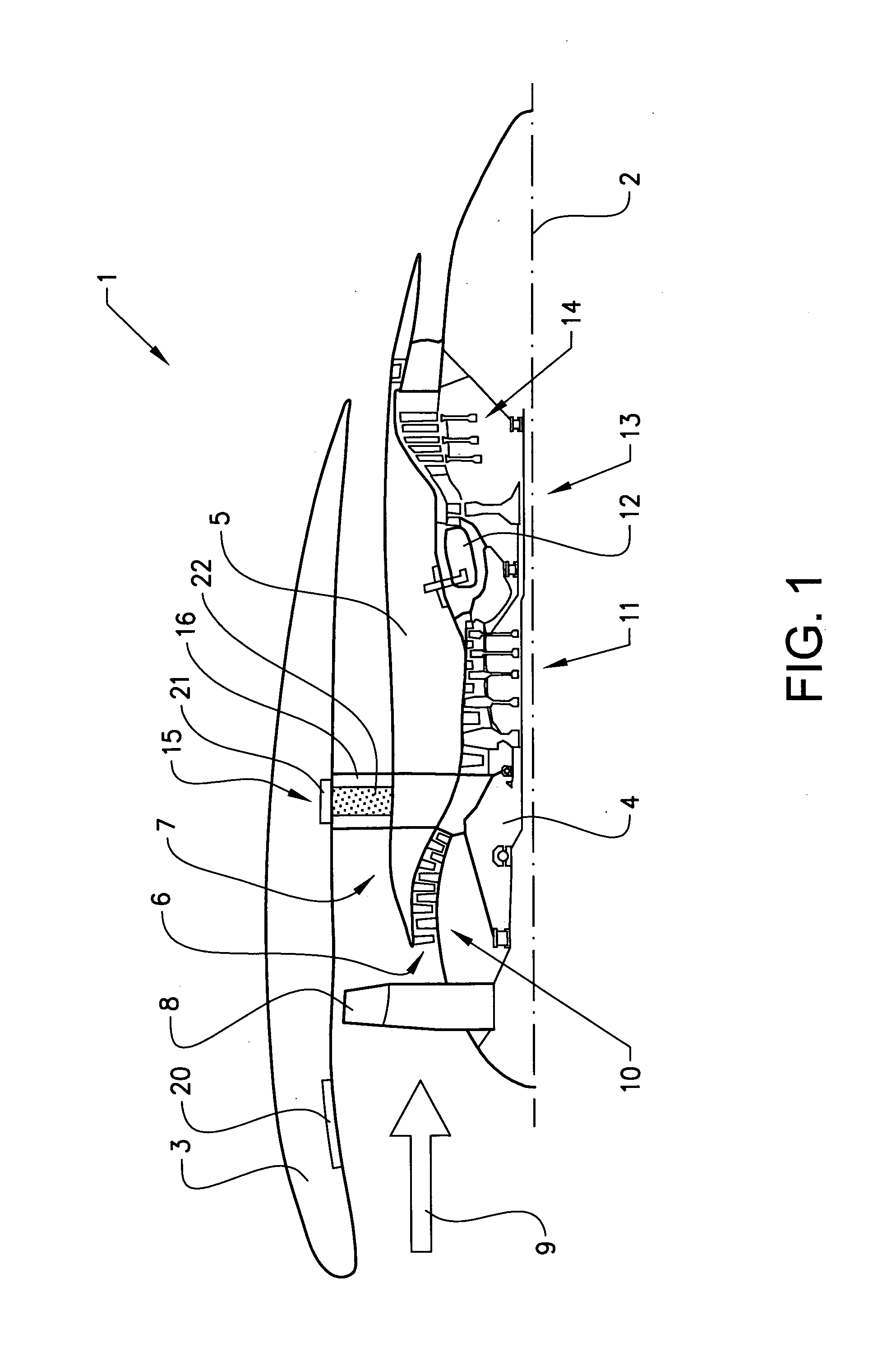
[0032]The invention will below be described for a turbofan gas turbine aircraft engine 1, which in FIG. 1 is circumscribed about an engine longitudinal central axis 2. The engine 1 comprises an outer casing or nacelle 3, an inner casing 4 and an intermediate casing 5 which is concentric to the first two casings and divides the gap between them into an inner primary gas channel 6 for the compression of air and a secondary channel 7 in which the engine bypass air flows. The casings are in turn made up of a plurality of components in the axial direction of the engine. Thus, each of the gas channels 6, 7 is annular in a cross section perpendicular to the engine longitudinal central axis 2.

[0033]The engine 1 comprises a fan 8 which receives ambient air 9, a booster or low pressure compressor (LPC) 10 and a high pressure compressor (HPC) 11 arranged in the primary gas channel 6, a combustor 12 which mixes fuel with the air pressurized by the high pressure compressor 11 for generating comb...


PUM


Abstract

A noise attenuation panel includes a first wall, a second wall and partition walls connected to the first and second walls and defining cells between the first and second walls. The first wall is provided with a plurality of through holes. At least two of the cells are interconnected via a communication hole. One of the through holes leads to a first of the at least two interconnected cells and a second of the interconnected cells is configured to prevent any gas flow through the second cell.

Description

BACKGROUND AND SUMMARY[0001]The present invention relates to a noise attenuation panel comprising a first wall, a second wall and partition walls connected to the first and second walls and defining cells between the first and second walls, wherein the first wall is provided with a plurality of through holes. The invention is further directed to a gas turbine component comprising a noise attenuation panel.[0002]The gas turbine component is configured for application in a gas turbine engine, and especially in an aircraft engine. Thus, the invention is especially directed to a jet engine. Jet engine is meant to include various types of engines, which admit air at relatively low velocity, heat it by combustion and shoot it out at a much higher velocity. Accommodated within the term jet engine are, for example, turbojet engines and turbofan engines. The invention will below be described for a turbofan-engine, but may of course also be used for other engine types.[0003]Said noise attenua...

Claims


Application Information

Patent Timeline
IPC IPC(8): E04B1/82
CPCF01D25/162F02C7/045G10K11/172Y02T50/672F01D9/041F05D2250/191F05D2250/283F05D2260/963F05D2260/96F02K1/827Y02T50/60
Inventor BURAK, MARKUS OLANDERERIKSSON, LARS-ERIK
Owner GKN AEROSPACE SWEDEN AB
Why Eureka
Try Eureka