Cavity filter, connector and manufacturing processes thereof

a technology of cavity filter and manufacturing process, applied in the field of communication, can solve the problems of difficult control of the powder layer, long production time, low efficiency and high production cost, and achieve the effect of improving the reliability of the connector in special environments, reducing the time needed for powder spraying, and improving the protection effect of the connector

Active Publication Date: 2017-01-10
ANHUI TATFOOK TECH CO LTD
View PDF31 Cites 2 Cited by
  • Summary
  • Abstract
  • Description
  • Claims
  • Application Information

AI Technical Summary

Benefits of technology

[0006]In view of this, a cavity filter, a connector and manufacturing processes thereof are provided in the present disclosure, which can simplify the production process, improve the “three-proofing” capabilities and reliability of the whole product, and reduce the labor intensity and the production cost.
[0008]In the connector of the present disclosure, the outer peripheral surface of the metal enclosure is provided with a restricting structure for preventing falling off of the non-metal layer, and the metal enclosure is closely joined with the non-metal layer by means of the restricting structure.
[0017]In the cavity filter of the present disclosure, the outer peripheral surface of the metal enclosure is provided with a restricting structure for preventing falling off of the non-metal layer, and the metal enclosure is closely joined with the non-metal layer by means of the restricting structure.
[0031]By disposing the non-metal layer outside the metal enclosure of the connector in the present disclosure, the moisture-proof capability, the salt-mist-proof capability, the mould-proof capability and the reliability of the connector in special environments can be enhanced. In the conventional connector, powders are sprayed to an outer surface of the connector to form a protection layer, but the thickness of the powder sprayed is difficult to control and this leads to a poor protection effect of the connector; and the time needed for powder spraying is relatively long and the process is complex; and moreover, the powder spraying is carried out manually, and the dusts produced cause high pollution to the environment and injury to the operation personnel. In contrast, the connector adopting the structure of the present disclosure can overcome these shortcomings. Specifically, the non-metal layer can be formed outside the metal enclosure through a die casting or injection molding process, which is simple and free of pollution to the environment, requires less human intervention, simplifies the operation procedures in the production of the connector and reduces the labor intensity; and meanwhile, the connector of the present disclosure is made partly of a metal and partly of a non-metal material, and the light weight and low cost of the non-metal material can reduce the weight and the production cost of the connector. Thereby, the present disclosure simplifies the manufacturing process, improves the “three-proofing” capabilities and the reliability of the whole product and, meanwhile, reduces the labor intensity and the production cost.

Problems solved by technology

However, this layer of powders is difficult to control and tends to fall off.
If the enclosures are fabricated through machining, the complex features (e.g., screws) of the enclosures of the connectors will lead to a long production time, low efficiency and a high production cost.
If the enclosures are fabricated through a die casting process, the resulting connectors will become unaesthetic and the “three-proofing” capabilities of the connectors will be degraded because of the coarse surface of the die-cast enclosures.
If the enclosures are fabricated through a die casting plus machining process, then the process route will become long and complex to cause a high production cost.
Accordingly, the conventional cavity filters and connectors thereof still present inconveniences and have shortcomings in practical use, so a need exists in the art to make an improvement on them.

Method used


Image

  • Cavity filter, connector and manufacturing processes thereof
  • Cavity filter, connector and manufacturing processes thereof
  • Cavity filter, connector and manufacturing processes thereof

Examples


Embodiment Construction

[0042]Hereinbelow, the technical solutions of the embodiments of the present disclosure will be clearly and fully described with reference to the attached drawings in the embodiments of the present disclosure. It shall be understood that, the embodiments described herein are only provided to illustrate rather than to limit the present disclosure.

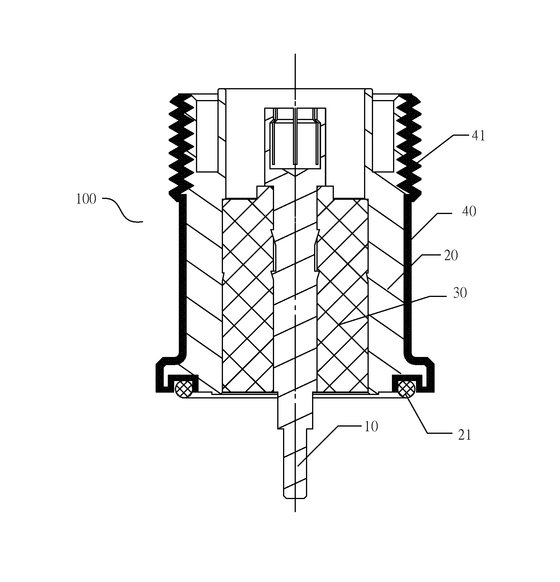
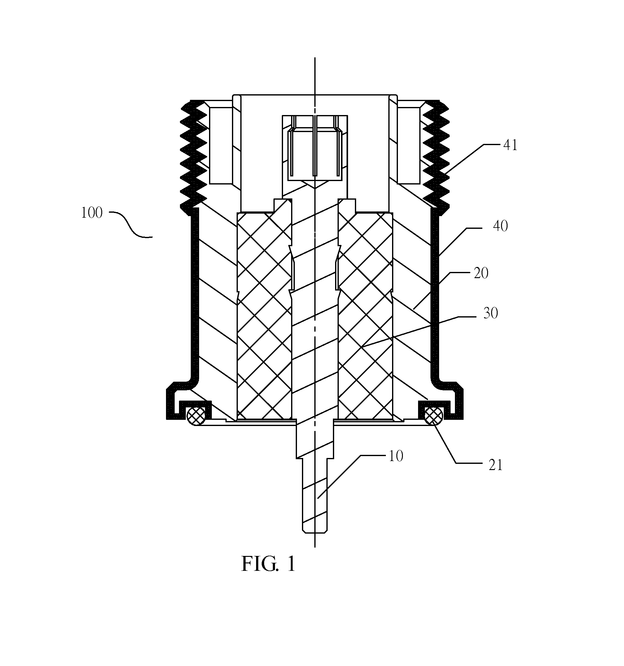
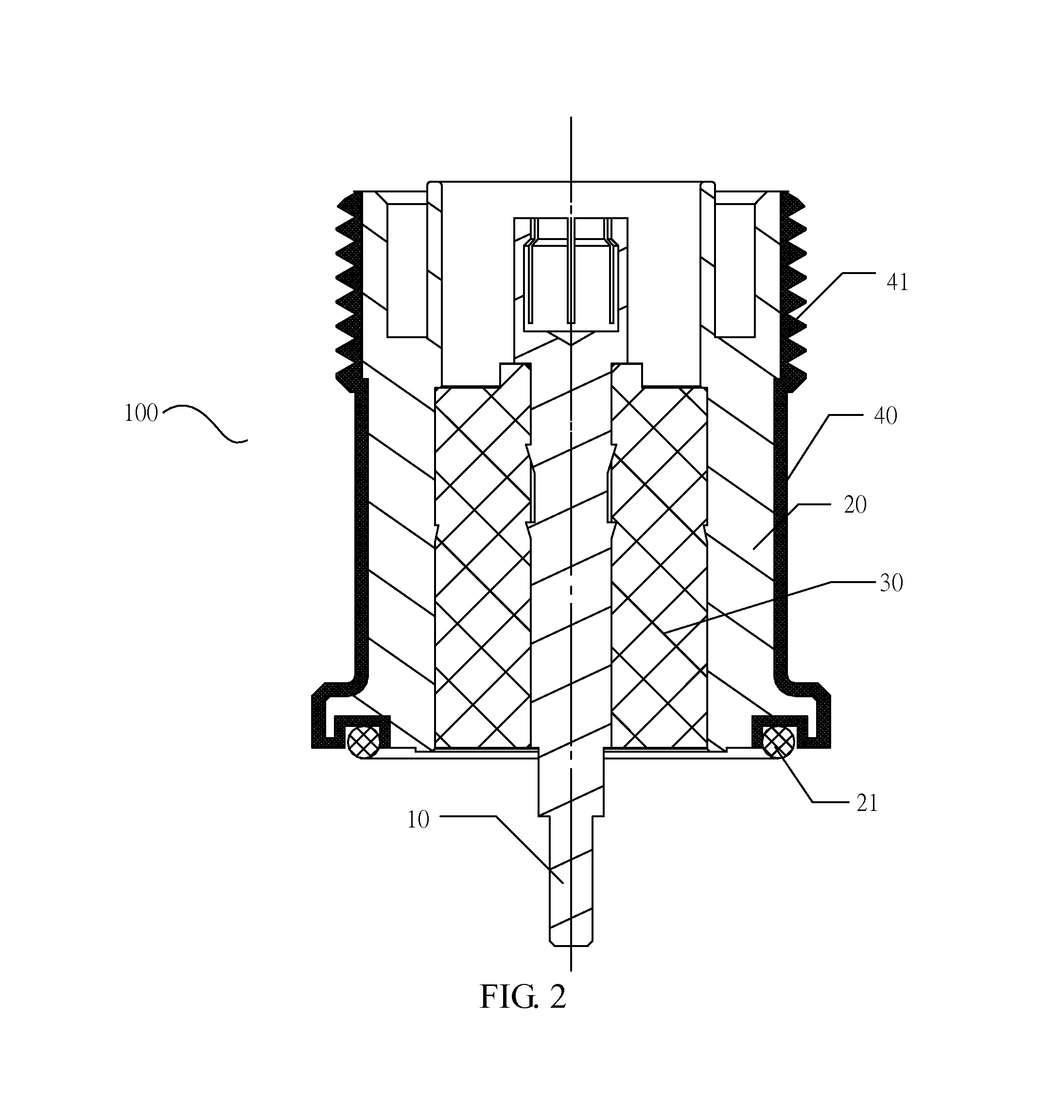
[0043]As shown in FIGS. 1˜8, a connector 100 of the present disclosure comprises an inner conductor 10 and a metal enclosure 20 disposed coaxially and an insulation medium 30 disposed between the metal enclosure 20 and the inner conductor 10, where a non-metal layer 40 is disposed to cover an outer peripheral surface of the metal enclosure 20.

[0044]By disposing the non-metal layer 40 outside the metal enclosure 20 of the connector 100 in the present disclosure, the moisture-proof capability, the salt-mist-proof capability, the mould-proof capability and the reliability of the connector 100 in special environments can be enhanced. In the conv...


PUM

PropertyMeasurementUnit
areaaaaaaaaaaa
diameteraaaaaaaaaa
radio frequencyaaaaaaaaaa

Abstract

The present disclosure relates to a cavity filter, a connector and manufacturing processes thereof. The cavity filter comprises a cavity, a cover plate and a connector disposed on the cavity or the cover plate; an end of the connector is connected with internal devices inside the cavity filter and the other end of the connector is connected with external communication devices; and the connector comprises an inner conductor and a metal enclosure disposed coaxially and an insulation medium disposed between the metal enclosure and the inner conductor, and a non-metal layer is disposed on an outer peripheral surface of the metal enclosure. The connector of the present disclosure is formed with a non-metal layer on the outer peripheral surface of the metal enclosure thereof, which can improve the moisture-proof capability, the salt-mist-proof capability, the mold-proof capability and the reliability of the connector and the cavity filter.

Description

CROSS REFERENCE TO RELATED APPLICATIONS[0001]The present application is a 35 U.S.C. §371 National Phase conversion of International (PCT) Patent Application No. PCT / CN2013 / 072329, filed on Mar. 8, 2013, the disclosure of which is incorporated by reference herein. The PCT International Patent Application was filed and published in Chinese.FIELD OF THE INVENTION[0002]The present disclosure relates to the technical field of communications, and more particularly, to a cavity filter, a connector and manufacturing processes thereof.BACKGROUND OF THE INVENTION[0003]As important components of communication modules, filters or duplexers are usually provided with connectors (e.g., 7 / 16 connectors, N-type connectors, etc.) for connection with other modules. The connectors are usually connected with the filters or duplexers by means of screws. In order to satisfy the radio frequency (RF) specifications and to match the conventional manufacturing processes (e.g., machining, die casting and elect...

Claims


Application Information

Patent Timeline
Patent Type & Authority Patents(United States)
IPC IPC(8): H01P5/00H01P7/06H01P1/207H01P11/00H01R13/52H01R24/40
CPCH01P5/00H01P1/207H01P7/06H01P11/00H01R13/5219H01R24/40Y10T29/4922H01R13/03H01R13/46H01R43/00
Inventor TONG, ENDONG
Owner ANHUI TATFOOK TECH CO LTD
Why Eureka
Try Eureka