Eureka AIR delivers breakthrough ideas for toughest innovation challenges, trusted by R&D personnel around the world.

Compact CMOS device isolation

a cmos device and compact technology, applied in the direction of semiconductor devices, electrical equipment, transistors, etc., can solve the problems of increasing the cost of the integrated circuit, occupying a large amount of silicon area, and low noise coupling between the substrate and the analog block

Active Publication Date: 2017-01-17
ALPHA & OMEGA SEMICON INC
View PDF14 Cites 4 Cited by
  • Summary
  • Abstract
  • Description
  • Claims
  • Application Information

AI Technical Summary

Benefits of technology

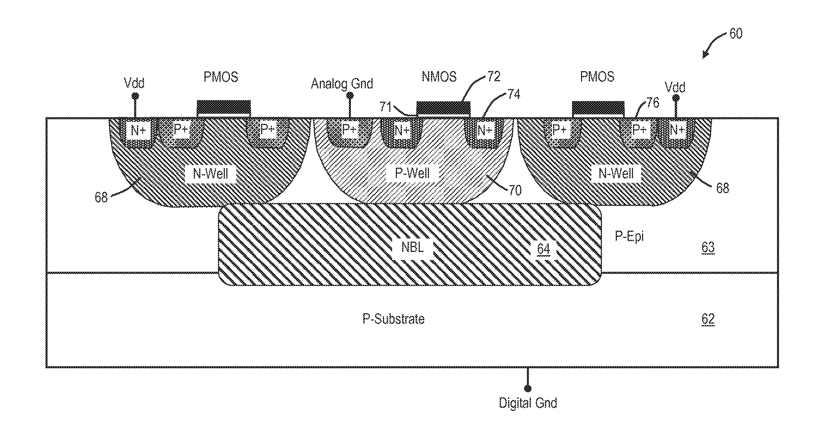
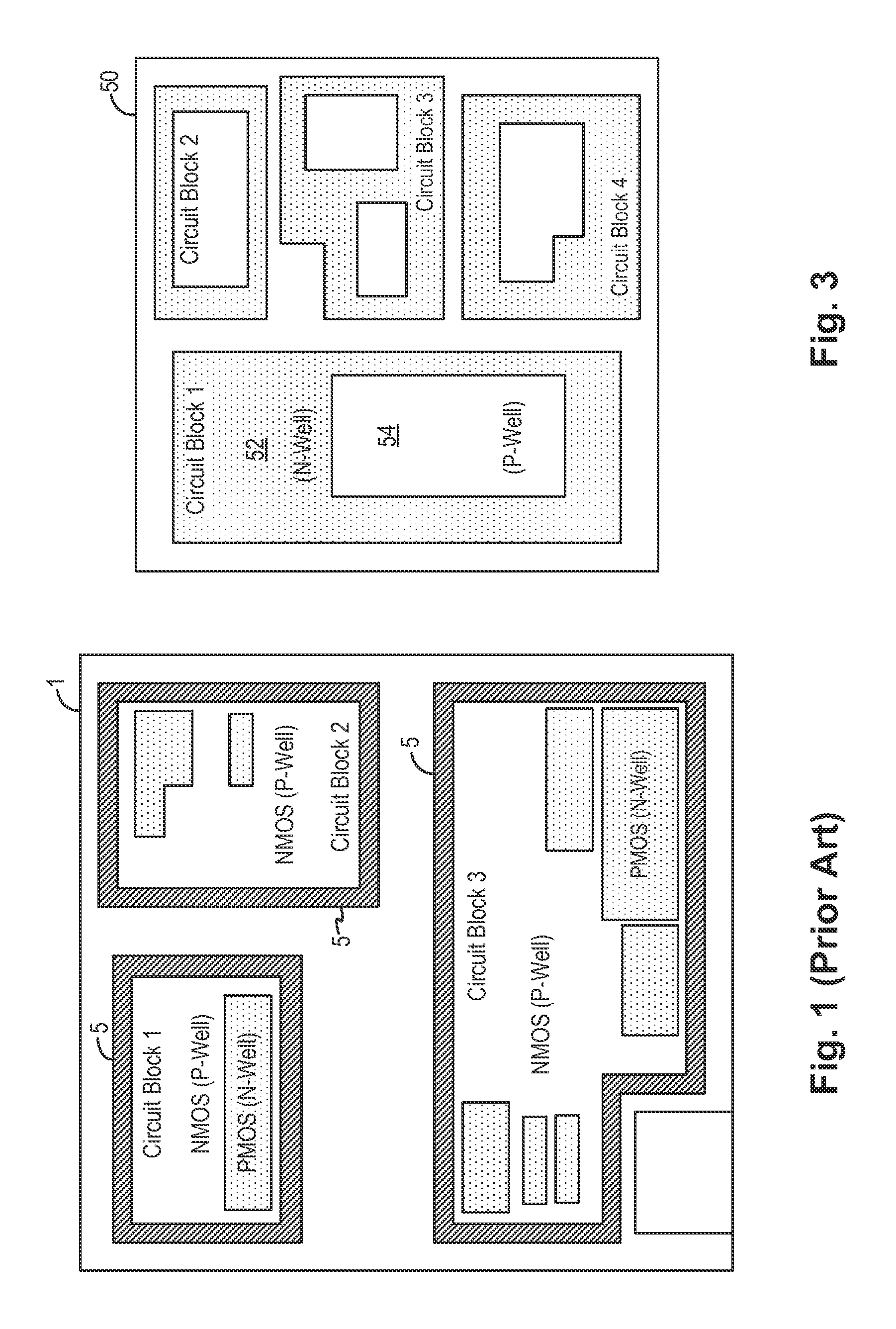
[0017]In embodiments of the present invention, the compact CMOS device isolation structure is applied for both analog circuit blocks and digital circuit blocks. Isolation of analog circuit blocks is important because the sensitive analog circuits formed therein need to be isolated from the noisy substrate, often connected to the digital ground. Isolation of the digital circuit blocks can be advantageous to keep the substrate less noisy which results in lower noise coupling from substrate to analog blocks.

Problems solved by technology

The substrate of the power integrated circuit, typically a P-type substrate, is typically connected to the digital ground which tends to be noisy due to the switching action of the digital clocking circuitry.
Although it is more critical to isolate the analog circuit blocks from the noisy P-type substrate, conventional integrated circuits typically isolate both the analog and the digital circuit blocks to keep the substrate less noisy which results in lower noise coupling from substrate to analog blocks.
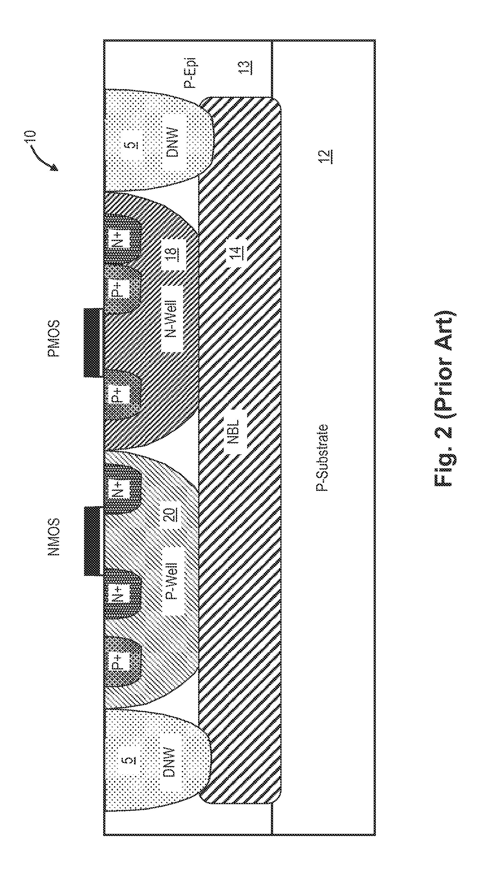
Although the conventional CMOS device isolation structure is effective, the isolation structure takes up large amount of silicon area because of the use of the deep N-well ring.
Thus, the die size for the integrated circuit formed using the conventional CMOS device isolation structure tends to be large, increasing the cost of the integrated circuit.

Method used


Image

  • Compact CMOS device isolation
  • Compact CMOS device isolation
  • Compact CMOS device isolation

Examples


Embodiment Construction

[0012]The invention can be implemented in numerous ways, including as a process; an apparatus; a system; and / or a composition of matter. In this specification, these implementations, or any other form that the invention may take, may be referred to as techniques. In general, the order of the steps of disclosed processes may be altered within the scope of the invention.

[0013]A detailed description of one or more embodiments of the invention is provided below along with accompanying figures that illustrate the principles of the invention. The invention is described in connection with such embodiments, but the invention is not limited to any embodiment. The scope of the invention is limited only by the claims and the invention encompasses numerous alternatives, modifications and equivalents. Numerous specific details are set forth in the following description in order to provide a thorough understanding of the invention. These details are provided for the purpose of example and the inv...


PUM


Abstract

An integrated circuit includes a first well of the first conductivity type formed in a semiconductor layer where the first well housing active devices and being connected to a first well potential, a second well of a second conductivity type formed in the semiconductor layer and encircling the first well where the second well housing active devices and being connected to a second well potential, and a buried layer of the second conductivity type formed under the first well and overlapping at least partially the second well encircling the first well. In an alternate embodiment, instead of the buried layer, the integrated circuit includes a third well of the second conductivity type formed in the semiconductor layer where the third well contains the first well and overlaps at least partially the second well encircling the first well.

Description

BACKGROUND OF THE INVENTION[0001]Monolithic Power Integrated Circuits (PICs) for high-voltage applications may sometimes integrate thereon analog and digital circuitry. For example, one type of power integrated circuits is a DC-to-DC converter which may integrate the controller and one or both of the power switches on a single integrated circuit. As thus integrated, CMOS devices forming the analog circuits in the power integrated circuit need to be isolated from the noisy substrate to avoid circuit malfunction due to noise. In particular, the analog circuits typically include sensitive circuitry such as bandgap, amplifier and sensing circuits. The digital circuits typically include the oscillator, logic circuitry and the PWM controller. Conventional power integrated circuit includes separate ground connection for the analog circuits (analog ground) and for the digital circuits (digital ground). The substrate of the power integrated circuit, typically a P-type substrate, is typically...

Claims


Application Information

Patent Timeline
Patent Type & Authority Patents(United States)
IPC IPC(8): H01L27/092H01L21/8238H01L21/761H01L29/10
CPCH01L27/0928H01L21/761H01L21/823878H01L21/823892H01L29/1083H01L27/092H01L29/0646
Inventor MALLIKARJUNASWAMY, SHEKAR
Owner ALPHA & OMEGA SEMICON INC
Why Eureka
Eureka Blog
Learn More