Traction control system and process for a machine having a work implement

a technology of traction control system and work implement, which is applied in the direction of tractors, mechanical machines/dredgers, transportation and packaging, etc., can solve the problems of cost prohibitive, tire or track failure, etc., and achieve the effect of reducing the torque of the powertrain componen

Active Publication Date: 2017-01-31
CATERPILLAR INC
View PDF10 Cites 20 Cited by
  • Summary
  • Abstract
  • Description
  • Claims
  • Application Information

AI Technical Summary

Benefits of technology

[0009]In one aspect, the disclosure describes a traction control process configured to limit slip of a machine having a work implement, including determining a motion of the machine with a machine motion sensor, determining whether the work implement of the machine is in an operational state with a work implement unit, determining a motion of a powertrain component with a powertrain motion sensor, comparing the motion of the machine determined by the machine motion sensor to the motion of the powertrain component determined by the powertrain motion sensor to determine slip with a machine powertrain controller, reducing a torque to the powertrain component when slip is determined by the machine powertrain controller, enabling the machine powertrain controller to reduce the torque when it is determined by the work implement unit that the work implement of the machine is operational, and disabling the machine powertrain controller from reducing the torque when it is determined by the work implement unit that the work implement of the machine is not operational.

Problems solved by technology

One problem that may become cost prohibitive during the lifetime of the machine is tire or track failure.
This cost of tire or track replacement for a wheel loader, wheel dozer, or tracked bulldozer may represent a large portion of the cost to operate the machine.
In this regard, a problem in the industry is that an operator of the machine is unable to ascertain in enough time to prevent such catastrophic tire failure because there is no sure indicator of a tire slippage until the damage has been realized.
This is because even a quarter of a rotation of a tire may result in a deep tear.
Such a deep tear lends itself to failure of the tire entirely.
Alternatively, all four tires may fail when the tires are spinning together, and therefore slight operator delayed reaction time to reduce the torque delivered to the tires is often too late.
A few devices or techniques for traction control for such machines have been developed that fail to address the above noted problems.
However this can be cost prohibitive as it requires multiple wheel speed sensors, knowledge of the machine's articulation angle, individual wheel speeds as well as a means to eliminate slip for each wheel.
However, prior art approaches, such as the system in the '002 patent, may be expensive to implement, are not configured to determine a state of the machine components for slip determination, such as pile engagement, and / or are not configured to determine state of the machine powertrain for slip determination.

Method used


Image

  • Traction control system and process for a machine having a work implement
  • Traction control system and process for a machine having a work implement
  • Traction control system and process for a machine having a work implement

Examples


Embodiment Construction

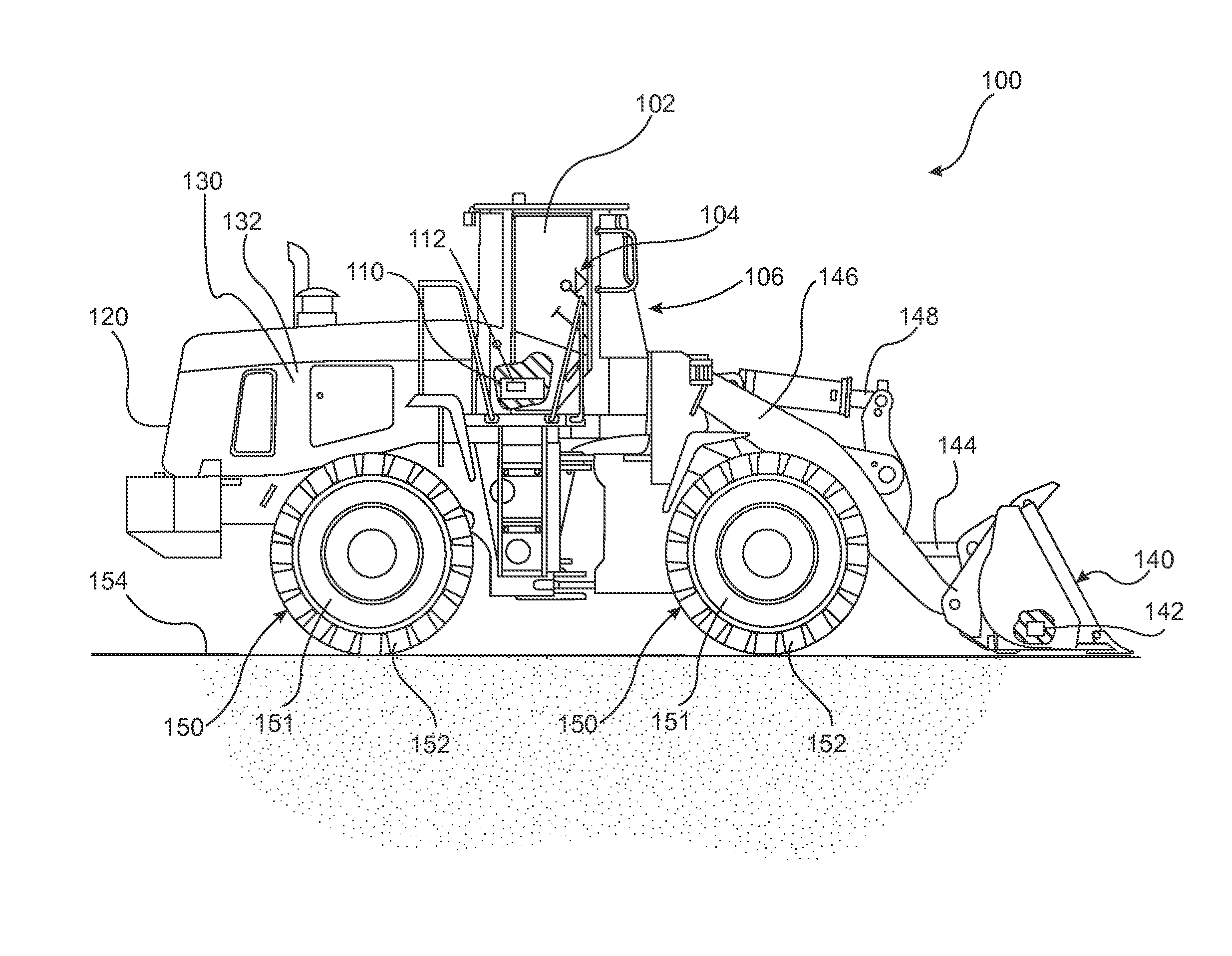
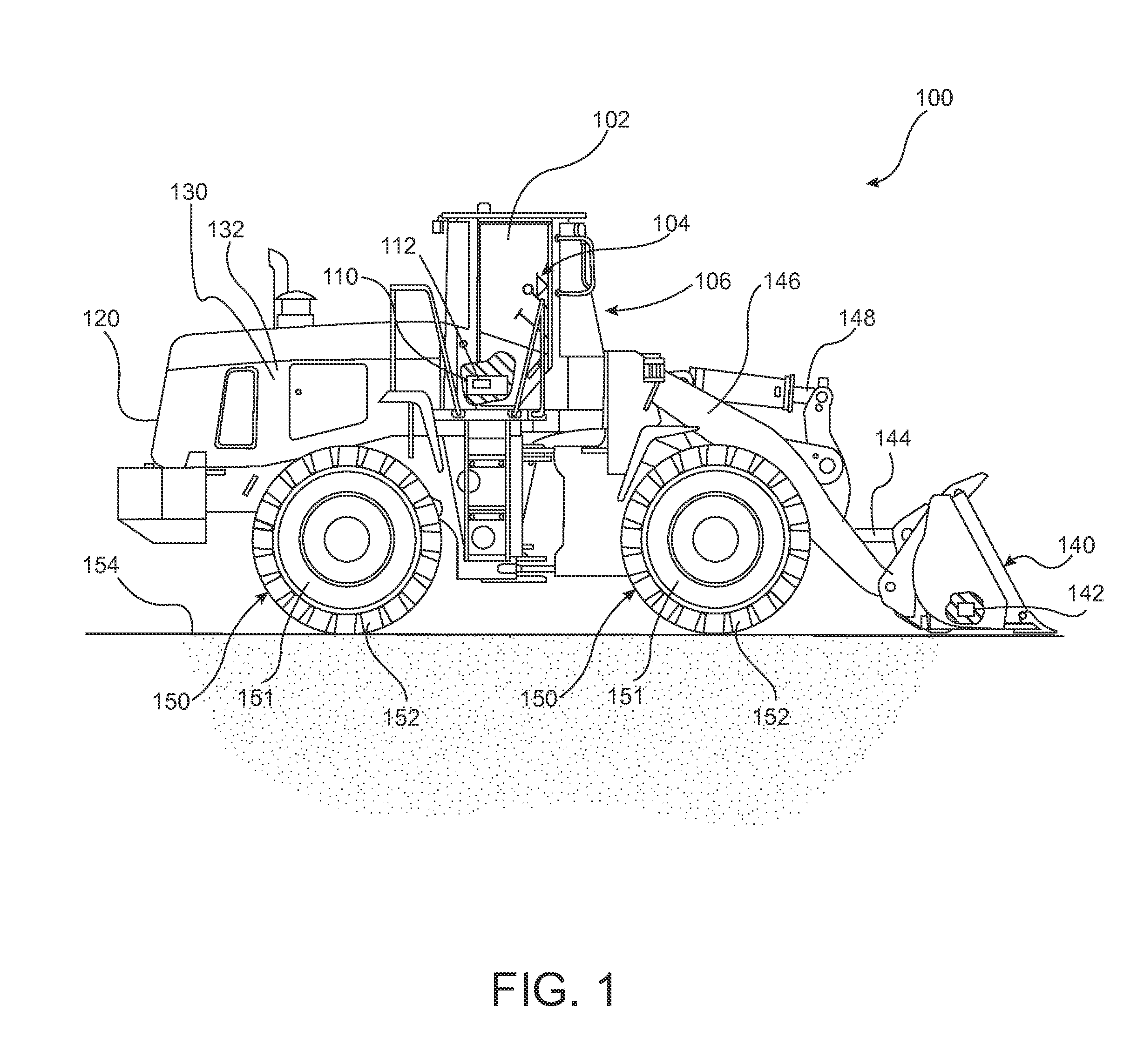
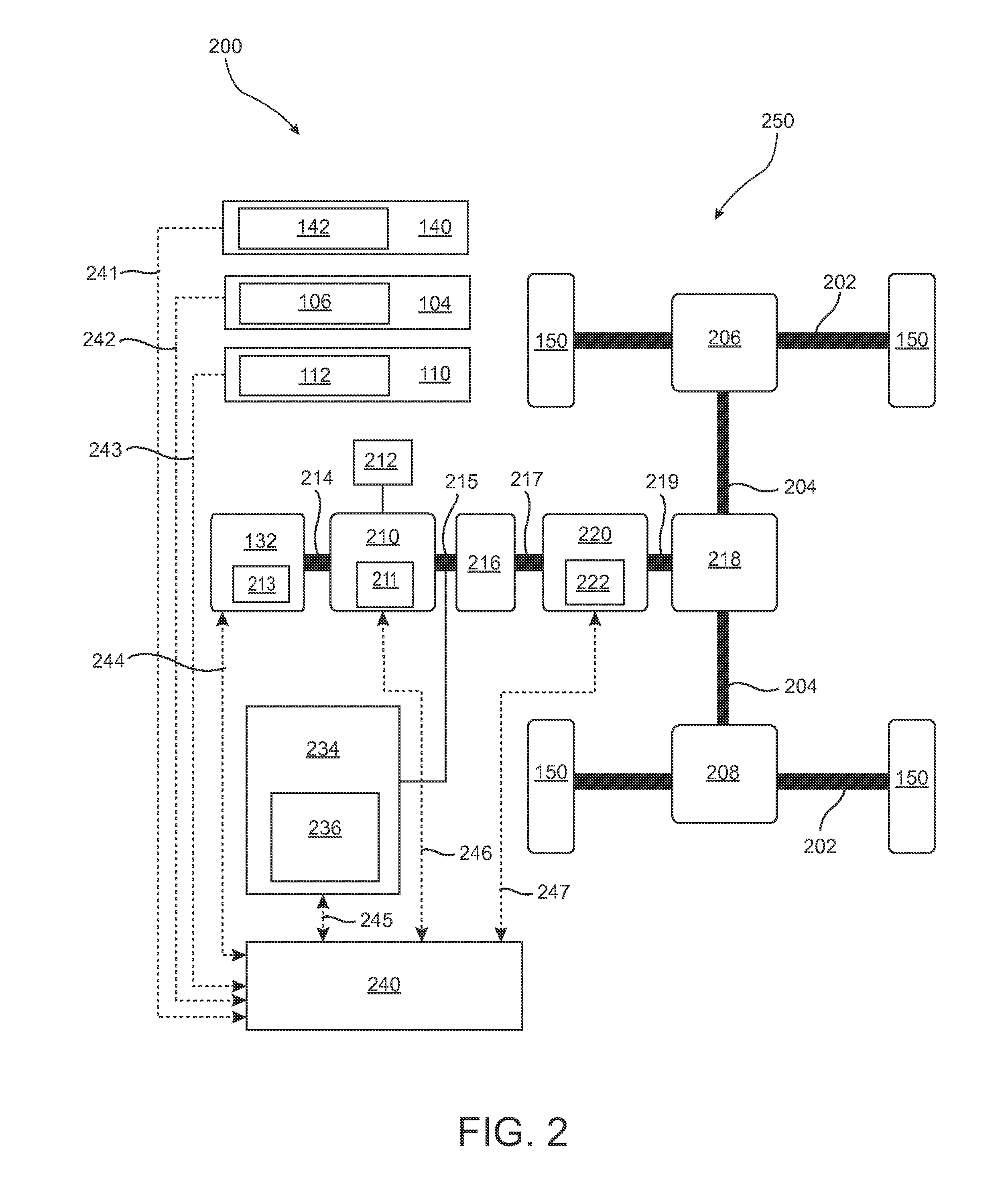
[0014]The present disclosure relates to a system and method for a traction control system and process that detects various inputs and responds by reducing torque in the powertrain system. In particular, one input may be indicative of an acceleration and / or speed of the powertrain determined by a sensor. Another input may be indicative of the acceleration and / or speed of the machine determined by an accelerometer. When the machine is operating without slipping, acceleration of the powertrain will have a linear relationship with the acceleration of the machine. During such operations, the traction control system would take no action. On the other hand when the machine is operating with slipping, acceleration of the powertrain will be greater, based on the linear relationship, than the acceleration of the machine. During such events, the traction control system will act to reduce slipping. Additionally, the traction control system may only be active when the machine is actively operati...


PUM


Abstract

A traction control system configured to limit slip by a machine having a work implement including a machine motion sensor configured to determine a motion of the machine, a work implement unit configured to determine whether the work implement is in an operational state, a powertrain motion sensor configured to determine a motion of a powertrain component, and a machine powertrain controller configured to determine slip by comparing the motion of the machine to the motion of the powertrain component, wherein the machine powertrain controller is configured to command a torque reduction to the powertrain component when slip is determined.

Description

TECHNICAL FIELD[0001]The disclosure is related to a traction control system and process for use in a machine, and more particularly a traction control system and process for a machine having a work implement.BACKGROUND[0002]Machines including large wheel loaders, wheel dozers, or tracked bulldozers may be used for engaging with high impact loads at a construction or mining worksite. Such use may be generally referred to as pile engagement. These machines benefit from high torque and engine speed when engaging with the pile of material. Often these machines are being operated on uneven or unpaved terrain, for example, for transporting a rock pile in a rock-filled mine. One problem that may become cost prohibitive during the lifetime of the machine is tire or track failure. For example, in a mining application, where a rock or other material pierces the tire while there is still a significant amount of tread left. The tire on a wheel may need replacement before a full life cycle of th...

Claims


Application Information

Patent Timeline
Patent Type & Authority Patents(United States)
IPC IPC(8): B60W30/184B60K28/16E02F9/26E02F9/20E02F3/34
CPCB60K28/165E02F9/2079E02F9/264B60W2300/17B60W2520/26B60W2520/105B60W2720/30E02F3/34B60Y2200/415B60Y2300/18175B60Y2300/42B60W10/02B60W10/04B60W30/18172B60W30/1886B60W2510/1045B60Y2200/412E02F9/205E02F9/265
Inventor MITCHELL, MICHAELTHOMSON, NORVAL
Owner CATERPILLAR INC
Why Eureka
Try Eureka